
Segmented magneto-conductive structure applied in rotating machines

a magnetic structure and rotating machine technology, applied in the direction of dynamo-electric machines, dynamo-electric components, magnetic circuit shapes/forms/constructions, etc., can solve the problems of increasing the price of electrical products and equipment driven by permanent magnetic motors, affecting the application of permanent magnetic motors, and increasing the price of electrical products and equipmen

Active Publication Date: 2013-05-16
IND TECH RES INST
View PDF4 Cites 40 Cited by
  • Summary
  • Abstract
  • Description
  • Claims
  • Application Information

AI Technical Summary

Benefits of technology

This patent describes a structure for rotating machines that involves a rotor and stator assembly. The rotor is made of non-oriented silicon steel while the stator is made of grain-oriented silicon steel. The rotor teeth are surrounded by the rotor yoke and extend along its radial direction. The stator yoke surrounds the rotor assembly along its rotational direction, and the stator teeth are placed between adjacent stator yoke components and extend along a radial direction. This structure results in a more compact and efficient motor design.

Problems solved by technology

However, about 97% of the production capacity of rare-earth permanent magnets comes from China, and therefore the unbalanced supply and demand of rare-earth materials causes the price hike.
As a result, applications of permanent magnetic motors are affected and prices of electrical products and equipments driven by permanent magnetic motors also increase.
In view of the abovementioned, it is a problem for manufacturers worldwide who require rare-earth permanent magnets to develop highly energy efficient equipments and products.

Method used


Image

  • Segmented magneto-conductive structure applied in rotating machines
  • Segmented magneto-conductive structure applied in rotating machines
  • Segmented magneto-conductive structure applied in rotating machines

Examples


Embodiment Construction

[0017]In the following detailed description, for purposes of explanation, numerous specific details are set forth in order to provide a thorough understanding of the disclosed embodiments. It will be apparent, however, that one or more embodiments may be practiced without these specific details. In other instances, well-known structures and devices are schematically shown in order to simplify the drawing.

[0018]Some embodiments of the disclosure provides a segmented magneto-conductive structure for applying in rotating machines in order to enhance an operational efficiency of rotating machines so as to achieve the purposes of energy-saving and better economic effectiveness.

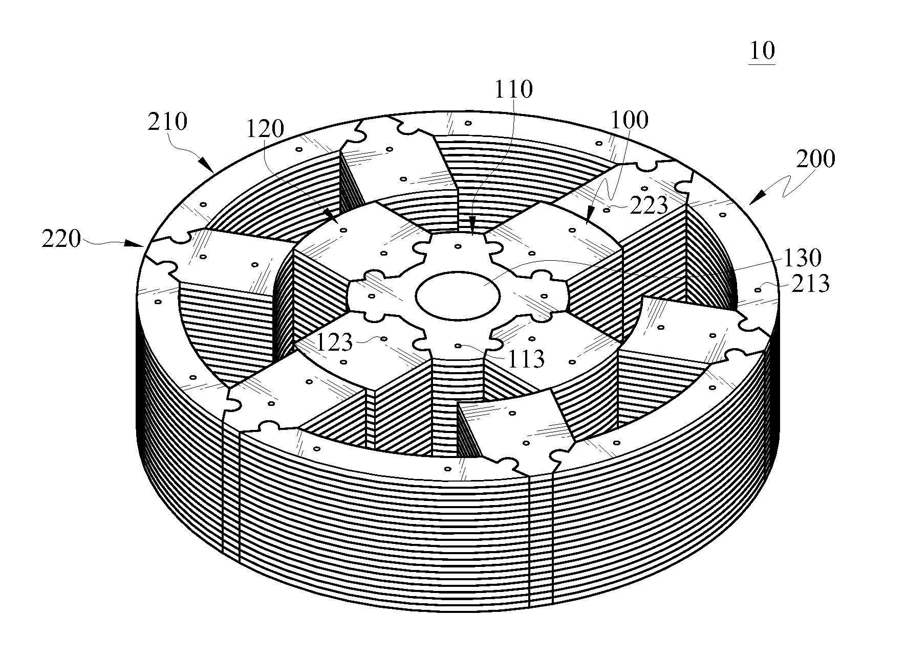
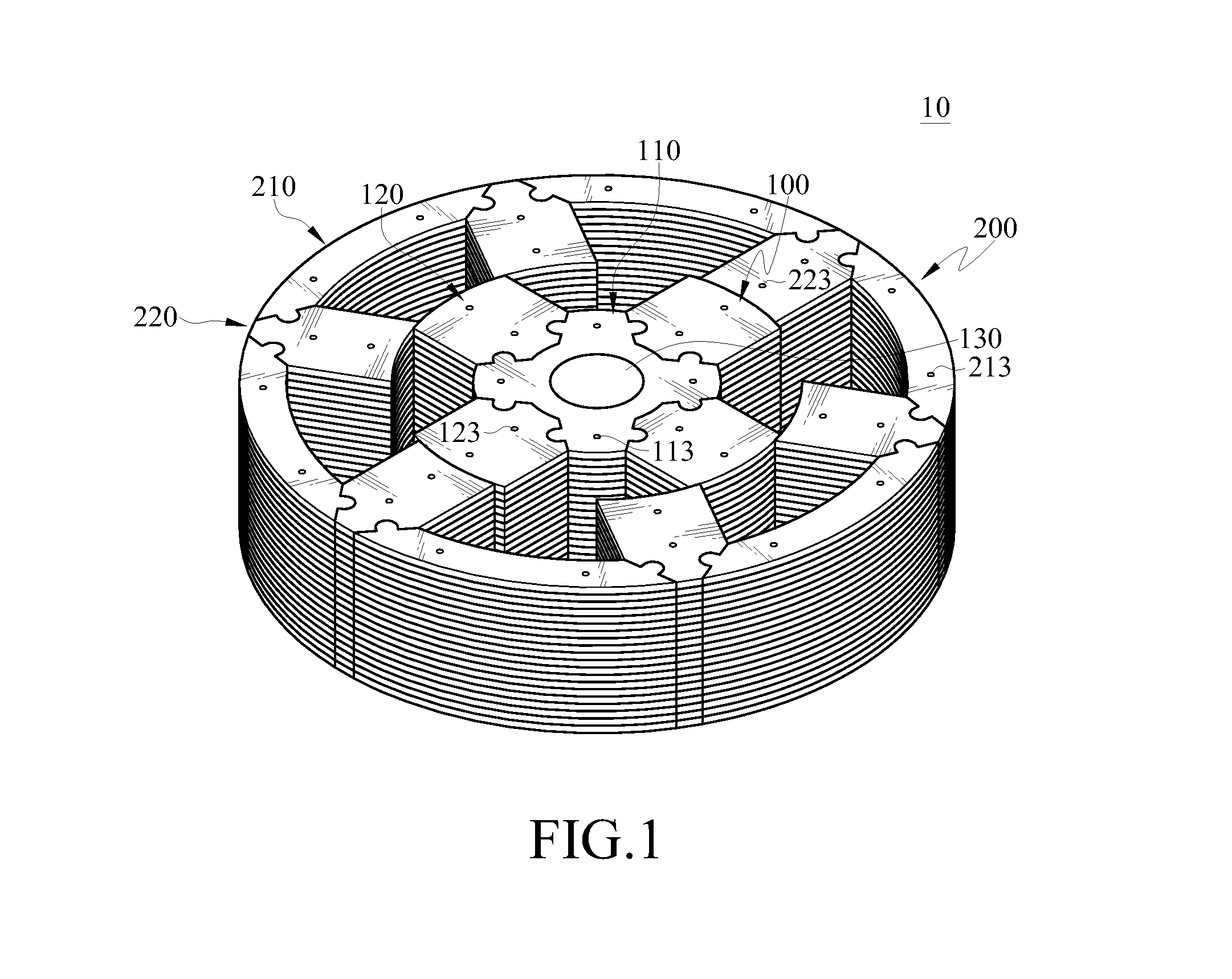
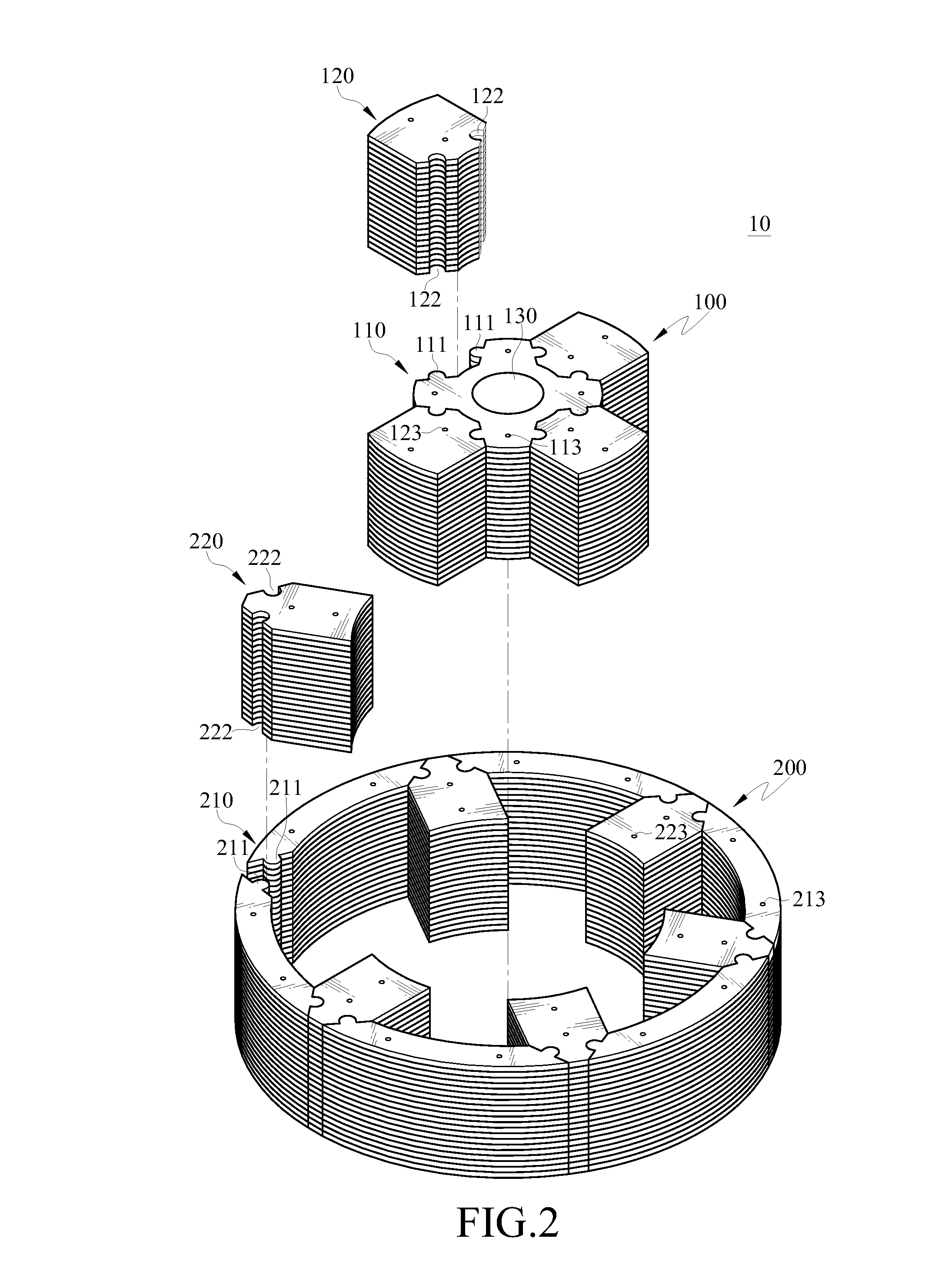
[0019]Referring to FIGS. 1, 2 and 3, FIG. 1 is a perspective structural view of a segmented magneto-conductive structure of an embodiment according to the disclosure, FIG. 2 is an exploded perspective view of a segmented magneto-conductive structure of an embodiment according to the disclosure, FIG. 3 is a top view...


PUM


Abstract

A segmented magneto-conductive structure applied in rotating machines comprises a rotor assembly and a stator assembly. The rotor assembly includes a rotor yoke component and a plurality of rotor teeth components. The rotor yoke component is made of non-oriented silicon steel. The rotor teeth components are made of grain-oriented silicon steel. The stator assembly includes a plurality of stator yoke components and a plurality of stator teeth components. The stator yoke components and the stator teeth components are made of grain-oriented silicon steel. Thereby, an operational efficiency of a motor applying the segmented magneto-conductive structure is enhanced.

Description

CROSS-REFERENCE TO RELATED APPLICATIONS[0001]This non-provisional application claims priority under 35 U.S.C. §119(a) on Patent Application No(s). 100141274 filed in Taiwan, R.O.C. on Nov. 11, 2011, the entire contents of which are hereby incorporated by reference.BACKGROUND[0002]1. Technical Field[0003]The present disclosure relates to a segmented magneto-conductive structure applied in rotating machines and more particularly to a segmented magneto-conductive structure employing grain-oriented silicon steel.[0004]2. Related Art[0005]Facing the cruel fact of the shortage of petrochemical energy globally, every major industrial country is especially taking the matters of energy development and control of energy consumption very seriously. Take home appliances as an example, energy consumed by indoors air conditioning, refrigerators, heat pumps of hot water systems and fans is amounted to approximately over 40% of a total household power consumption. As for the commercial and industri...

Claims


Application Information

Patent Timeline
Patent Type & Authority Applications(United States)
IPC IPC(8): H02K1/08
CPCH02K1/02H02K1/24H02K1/148
Inventor YANG, CHUN-CHUNGYU, SHOU-LONG
Owner IND TECH RES INST
Learn More