
System and method for beamforming in soft-field tomography

a soft-field tomography and beamforming technology, applied in the field of data reconstruction systems and methods, can solve the problems of small changes in measurement data, large changes in measured data, and low signal-to-noise ratio to accurately identify impedances

Active Publication Date: 2013-05-02
GENERAL ELECTRIC CO
View PDF3 Cites 4 Cited by
  • Summary
  • Abstract
  • Description
  • Claims
  • Application Information

AI Technical Summary

Benefits of technology

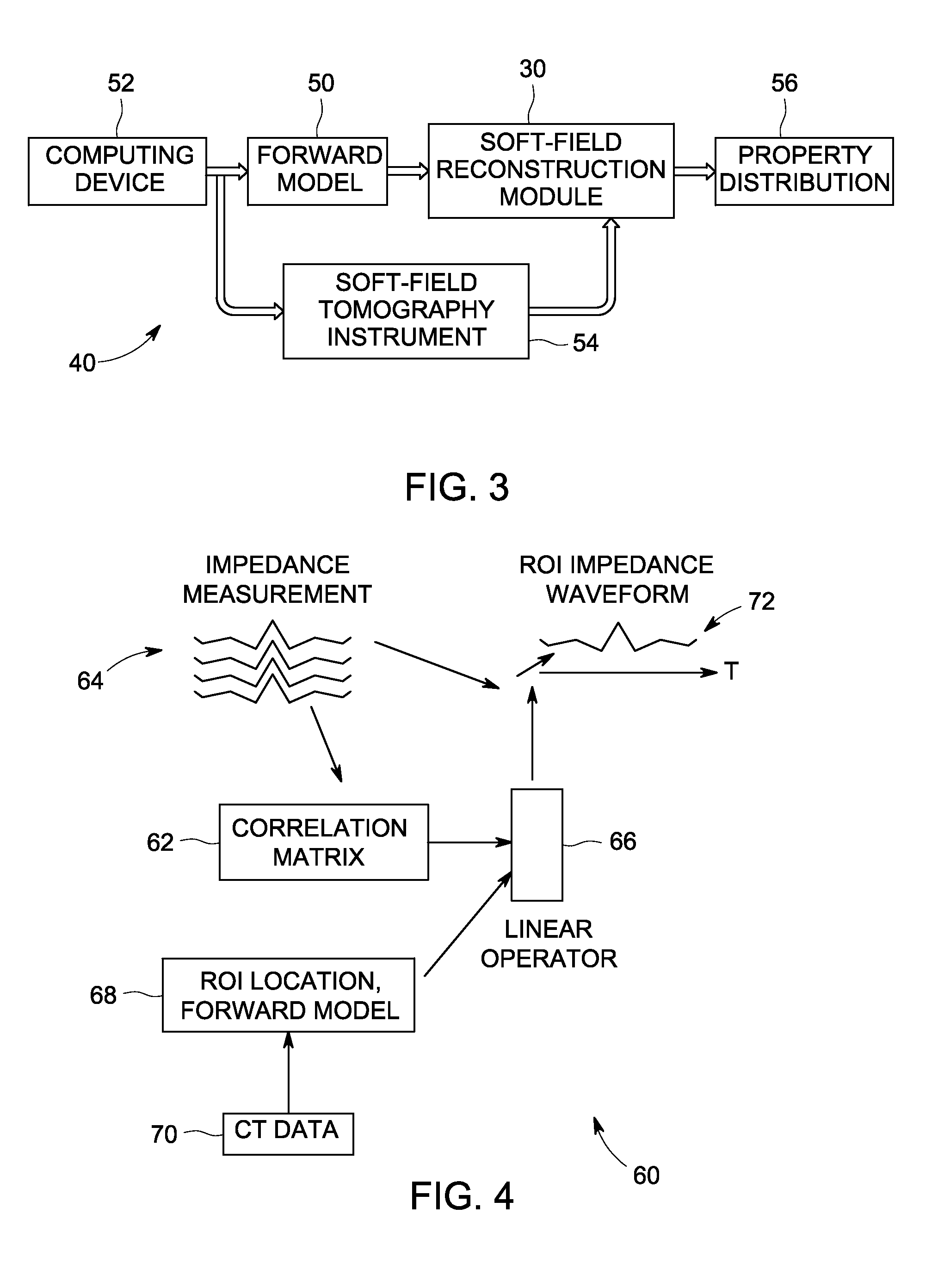
The patent describes a soft-field tomography system and a method for using it to determine the distribution of electrical properties in an object. The system includes a plurality of transducers that generate excitation signals with a specific frequency component, which are applied to the object using the transducers. The system measures the response of the object to the excitation using response detectors and a soft-field reconstruction module, which uses an Electrical Impedance Spectroscopy (EIS) beamformer to reconstruct the property distribution of the object. The technical effects of the system and method include improved accuracy in determining the electrical properties of objects using a non-destructive and non-invasive means, with potential applications in areas such as medical diagnostics and quality control in manufacturing processes.

Problems solved by technology

The inverse problem in EIS is to determine the spatial distribution of complex conductivities that give rise to the difference between measured data and the predicted model data.
The EIS inverse problem is highly ill-posed in that large perturbations in the conductivity distribution may result in small changes in the measurement data.
Similarly, small changes or errors in the applied excitation may result in large changes in the measured data.
In some applications, such as stroke detection, the signal-to-noise ratio may be too low to accurately identify the impedances.

Method used


Image

  • System and method for beamforming in soft-field tomography
  • System and method for beamforming in soft-field tomography
  • System and method for beamforming in soft-field tomography

Examples


Embodiment Construction

[0016]The foregoing summary, as well as the following detailed description of certain embodiments, will be better understood when read in conjunction with the appended drawings. To the extent that the figures illustrate diagrams of the functional blocks of various embodiments, the functional blocks are not necessarily indicative of the division between hardware circuitry. Thus, for example, one or more of the functional blocks (e.g., processors, controllers, circuits or memories) may be implemented in a single piece of hardware or multiple pieces of hardware. It should be understood that the various embodiments are not limited to the arrangements, component / element interconnections and instrumentality shown in the drawings.

[0017]As used herein, a module or step recited in the singular and proceeded with the word “a” or “an” should be understood as not excluding plural of said elements or steps, unless such exclusion is explicitly stated. Furthermore, references to “one embodiment” a...


PUM


Abstract

A system and method for beamforming in soft-field tomography are provided. One soft-field tomography system includes a plurality of transducers configured for positioning proximate a surface of an object and one or more excitation drivers coupled to the plurality of transducers and configured to generate excitation signals for the plurality of transducers. The excitation signals include at least one frequency component. The soft-field tomography system further includes one or more response detectors coupled to the plurality of transducers and configured to measure a response of the object at the plurality of transducers to the excitation applied by the plurality of transducers based on the excitation signals. The soft-field tomography system also includes a soft-field reconstruction module configured to reconstruct a property distribution based on the excitation signals and the measured response using an Electrical Impedance Spectroscopy (EIS) beamformer.

Description

BACKGROUND[0001]The subject matter disclosed herein relates generally to data reconstruction systems and methods, and more particularly to systems and methods to reconstruct data in soft-field tomography.[0002]Soft-field tomography, such as Electrical Impedance Spectroscopy (EIS) (also referred to as Electrical Impedance Tomography (EIT)), diffuse optical tomography, elastography, and related modalities may be used to measure the internal properties of an object, such as the electrical properties of materials comprising internal structures of an object (e.g., a region of a human body). For example, in EIS systems, an estimate is made of the distribution of electrical conductivities of the internal structures. Such EIS systems reconstruct the conductivity and / or permittivity of the materials within the area or volume based on an applied excitation (e.g., current) and a measured response (e.g., voltage) typically acquired at a surface of the area or volume. Visual distributions of the...

Claims


Application Information

Patent Timeline
Patent Type & Authority Applications(United States)
IPC IPC(8): A61B5/053A61B6/00A61B6/03
CPCA61B5/0536
Inventor UUTELA, KIMMO HENRIK
Owner GENERAL ELECTRIC CO
Learn More