
Circuit for autoregulating the oscillation frequency of an oscillating mechanical system and device including the same

a technology of oscillating mechanical system and circuit, which is applied in the direction of electric winding, instruments, and horology, can solve the problems of high cost, long manufacturing time and high cost, and complicated making of this type of generator and regulating circuit, so as to reduce the dimension of the oscillating mechanical system

Active Publication Date: 2013-05-02
THE SWATCH GRP RES & DEVELONMENT LTD
View PDF8 Cites 16 Cited by
  • Summary
  • Abstract
  • Description
  • Claims
  • Application Information

AI Technical Summary

Benefits of technology

The patent describes an invention that allows for a small and compact circuit to regulate the frequency of an oscillating mechanical system, such as in a wristwatch. This is accomplished by connecting an oscillator stage and a MEMS resonator in a way that allows for easy integration with other components of the circuit. The technical effect is that the size of the circuit is reduced, making it easier to mount in a wristwatch.

Problems solved by technology

However in the case of a wristwatch, all these additional regulating elements occupy considerable space inside the watch case, and lead to relatively long manufacturing time and high cost.
It can be complicated to make this type of generator and regulating circuit.
Moreover, the magnetic field of the rotating magnets may cause interference in some nearby ferromagnetic parts.
However, in this Patent document, no mention is made of regulating the oscillation frequency of the balance with the balance spring using an autoregulating circuit, which is a disadvantage.
With the proposed electronic circuit it is not possible to devise a very compact oscillating mechanical system with the regulating circuit in a manner that is easily accomplished, which constitutes a drawback.

Method used


Image

  • Circuit for autoregulating the oscillation frequency of an oscillating mechanical system and device including the same
  • Circuit for autoregulating the oscillation frequency of an oscillating mechanical system and device including the same
  • Circuit for autoregulating the oscillation frequency of an oscillating mechanical system and device including the same

Examples


Embodiment Construction

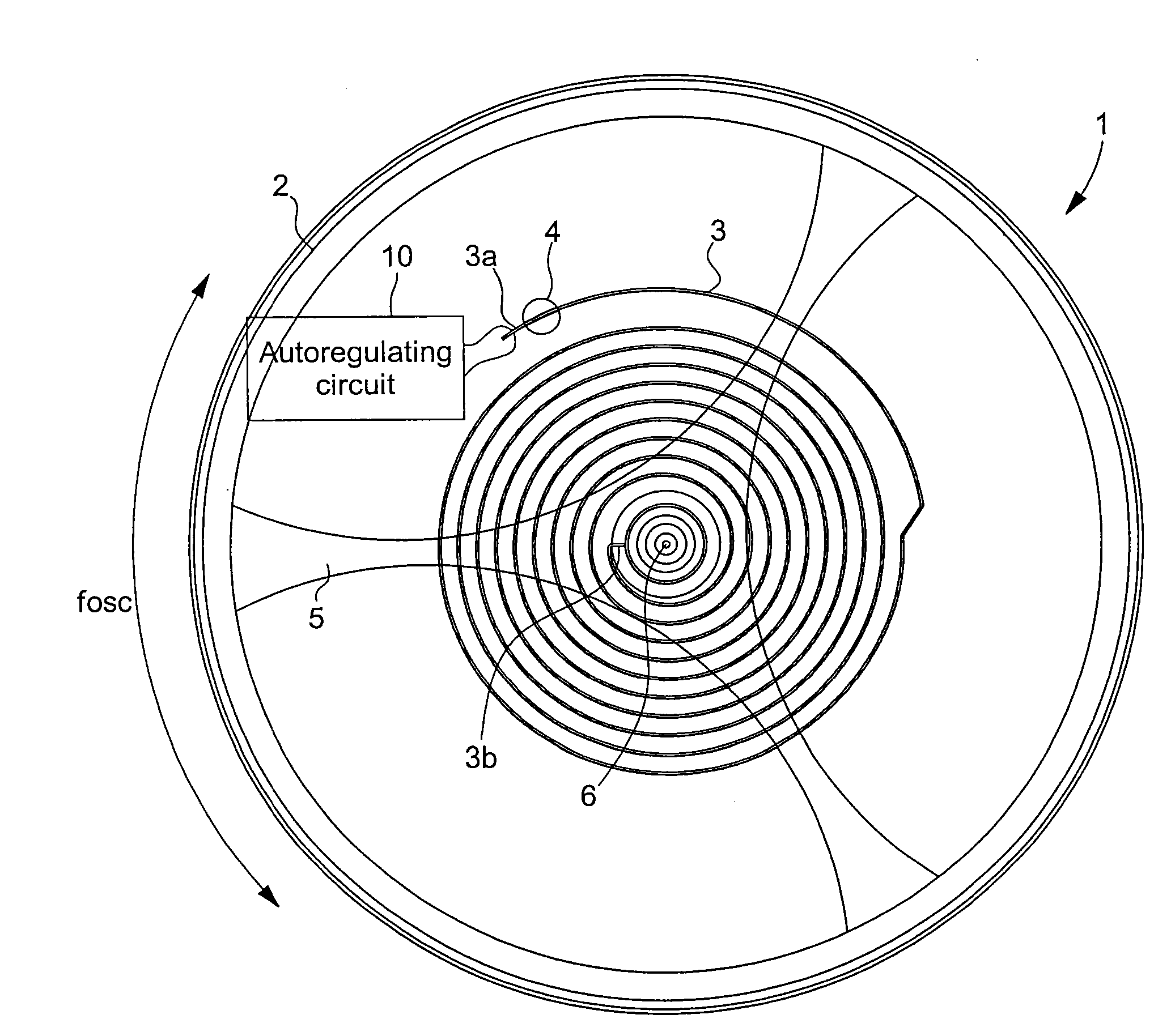
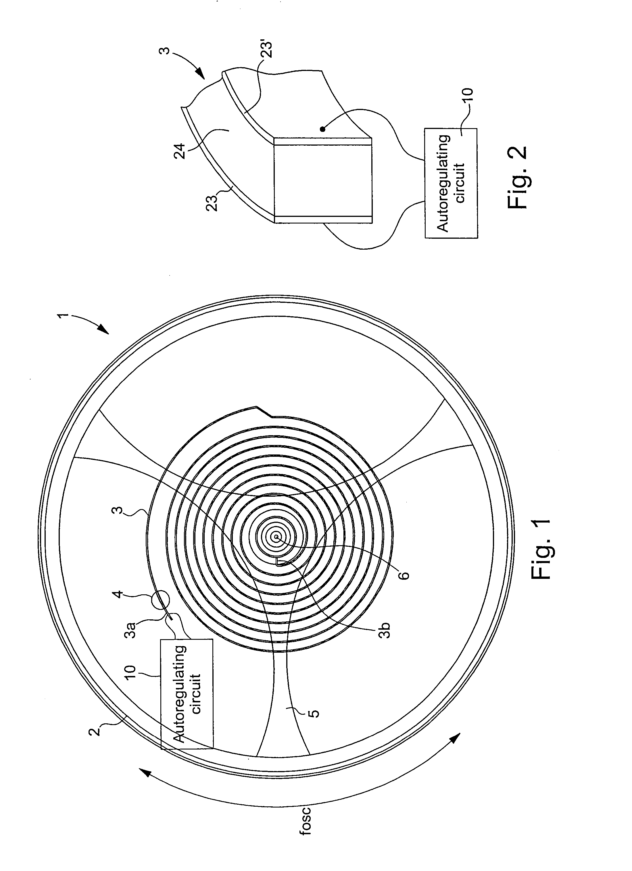
[0028]In the following description, all those electronic components of the oscillation frequency autoregulating circuit for an oscillating mechanical system that are well known to those skilled in the art in this technical field will be described only in a simplified manner. As described below, the autoregulating circuit is mainly used for regulating the oscillation frequency of a balance on which there is mounted a balance spring with a piezoelectric or electroactive polymer element. However, other oscillating mechanical systems may also be envisaged, for example an acoustic system such as a tuning fork, but in the following description, reference will be made only to an oscillating mechanical system in the form of a balance with a balance spring comprising a piezoelectric element or electroactive polymer (EAP) element.

[0029]FIG. 1 shows a device 1, which includes an oscillating mechanical system 2, 3 and a circuit 10 for autoregulating the oscillation frequency fosc of the oscilla...


PUM


Abstract

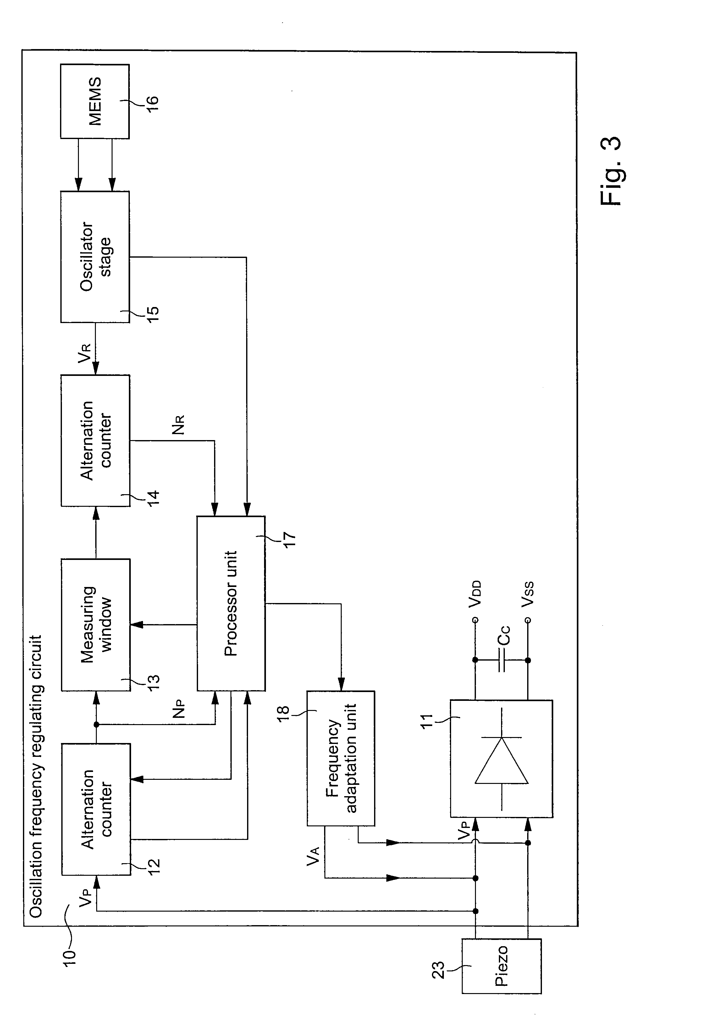
The autoregulating circuit regulates the oscillation frequency of an oscillating mechanical system, such as a balance having a balance spring. A piezoelectric element is mounted on the oscillating balance spring to generate an alternating voltage and connected to the autoregulating circuit, which rectifies the alternating voltage and regulates the alternating voltage frequency. The rectified voltage is stored in a capacitor to power the autoregulating circuit. The autoregulating circuit includes an oscillator stage connected to a MEMS resonator for supplying a reference signal, a means for comparing the frequency of the alternating voltage to the reference signal frequency, and a frequency adaptation unit for supplying a frequency adaptation signal to the piezoelectric element according to the result from the comparison means, to regulate the oscillation frequency of the balance. The electronic components of the autoregulating circuit form a single electronic module.

Description

[0001]This application claims priority from Swiss Patent Application No. 01741 / 11 filed Oct. 28, 2011, the entire disclosure of which is incorporated herein by reference.FIELD OF THE INVENTION[0002]The invention concerns a circuit for autoregulating the oscillation frequency of an oscillating mechanical system.[0003]The invention also concerns a device comprising the oscillating mechanical system and the circuit for autoregulating the oscillation frequency of the oscillating mechanical system.BACKGROUND OF THE INVENTION[0004]In the field of horology, the oscillating mechanical system may be a balance on which a balance spring is mounted, one end of which is secured to the rotating balance staff and the other end of which is secured to a fixed element of a bottom plate. The oscillation of the mechanical system is maintained via an energy source which is generally mechanical. This energy source may be, for example, a barrel driving a gear train with an escape wheel cooperating with a ...

Claims


Application Information

Patent Timeline
IPC IPC(8): G04C3/04
CPCG04C3/042G04C11/002G04D7/10G04B18/00H03H9/02409G04B17/06G04C3/04G04C3/047G04C3/067G04C3/068G04C3/069
Inventor WILLEMIN, MICHELMARTIN, JEAN-CLAUDE
Owner THE SWATCH GRP RES & DEVELONMENT LTD
Learn More