Eureka AIR delivers breakthrough ideas for toughest innovation challenges, trusted by R&D personnel around the world.

Time Delay With Control Voltage Sensing

a technology of time delay and control voltage, which is applied in the direction of space heating and ventilation control systems, lighting and heating apparatuses, and compressor types, etc., can solve the problems of compressor stalling, protection devices may not be able to prevent thermal damage to compressors, and the time necessary to trigger protection devices may be multiplied

Active Publication Date: 2013-05-02
TRANE INT INC
View PDF11 Cites 20 Cited by
  • Summary
  • Abstract
  • Description
  • Claims
  • Application Information

AI Technical Summary

Benefits of technology

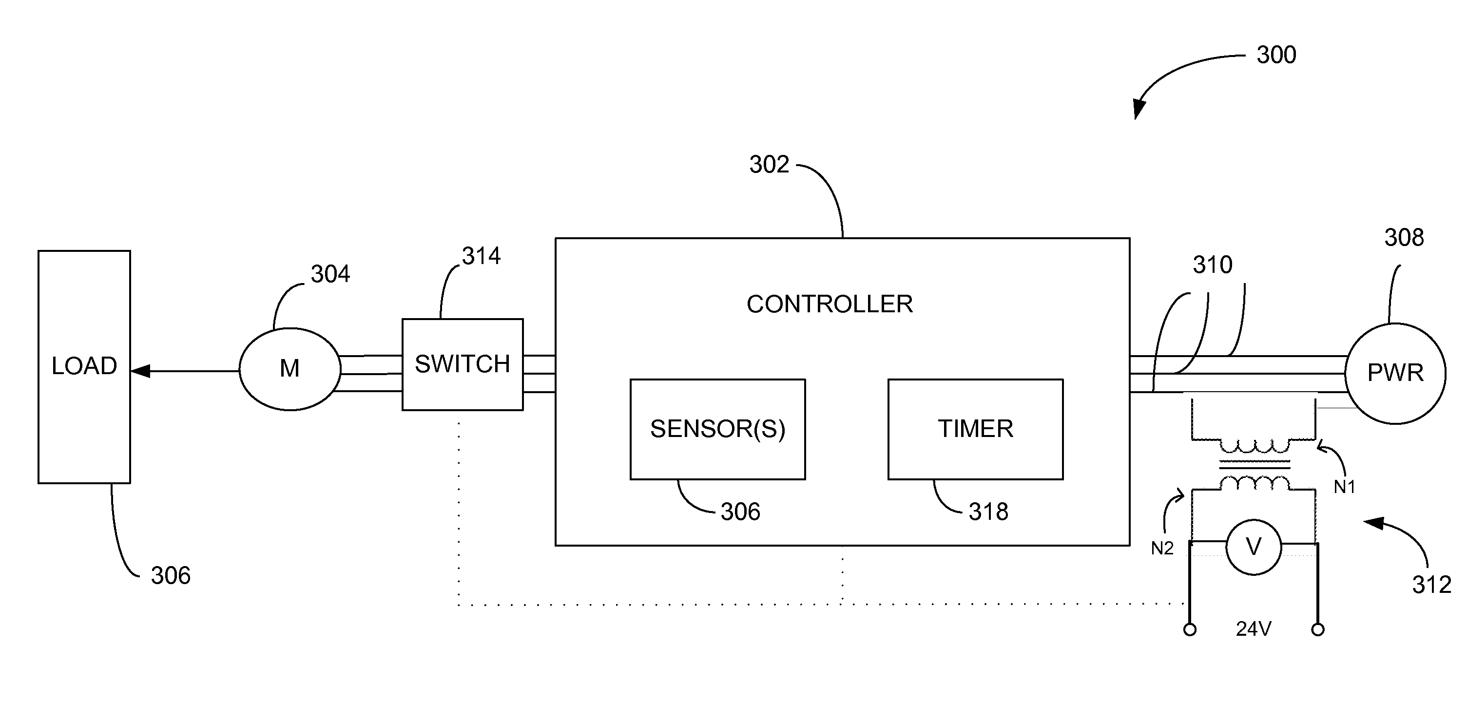
The present disclosure describes a heating, ventilating, and air conditioning (HVAC) system that includes a power source for supplying line voltage to an electric motor. The system includes a controller that receives a signal from a sensor that monitors the control voltage. The controller delays the supply of power to the motor and can de-energize the motor if there is no increase in control voltage within a set time period. This allows for safer and more efficient operation of the air conditioning unit.

Problems solved by technology

If a compressor is forced to operate at reduced voltage levels for a prolonged duration, the compressor may eventually stall.
However, the time necessary to trigger such protection devices may be multiplied when compressors stall at reduced line voltages such as 170 volts or less.
For instance, it may take a protection device about three to five times longer to trip the compressor in these situations, and therefore, the protection device may be unable to prevent thermal damage to the compressor.
Furthermore, when multiple compressors go offline due to situations such as brownouts, many of the compressors may return online at similar times. In such situations, the compressors may draw substantial quantities of current, thereby reducing the line voltage as described above.
As a result, widespread power outages may occur if the electrical grid cannot satisfy the overall demand.
Similarly, when compressors attempt to simultaneously return online once power is restored following a blackout, a subsequent blackout may occur due to the excessive power demanded to restart the compressors.

Method used


Image

  • Time Delay With Control Voltage Sensing
  • Time Delay With Control Voltage Sensing
  • Time Delay With Control Voltage Sensing

Examples


Embodiment Construction

[0017]It should be understood at the outset that although an illustrative implementation of one or more embodiments are provided below, the disclosed systems and / or methods may be implemented using any number of techniques, whether currently known or in existence. The disclosure should in no way be limited to the illustrative implementations, drawings, and techniques illustrated below, including the exemplary designs and implementations illustrated and described herein, but may be modified within the scope of the appended claims along with their full scope of equivalents.

[0018]Disclosed herein is a system and method for controlling operation of an air conditioning unit. In an embodiment, the system comprises a controller configured to monitor a supply of control voltage that is derived from line voltage, which supplies power to a motor. In response to detecting a reduction in control voltage, the controller may deactivate the motor if an increase in control voltage is not detected w...


PUM


Abstract

A method is provided for controlling operation of an air conditioning unit. The method comprises supplying line voltage to activate a motor configured to operate the air conditioning unit, and monitoring a supply of control voltage in order to control operation of the air conditioning unit, the supply of control voltage being derived from line voltage. In response to detecting a control voltage below a predetermined threshold and / or by a predetermined percentage, a time delay is initiated. The method further comprises deactivating the motor if a predetermined increase in control voltage is not detected before the time delay expires.

Description

CROSS-REFERENCE TO RELATED APPLICATIONS[0001]Not applicable.STATEMENT REGARDING FEDERALLY SPONSORED RESEARCH OR DEVELOPMENT[0002]Not applicable.REFERENCE TO A MICROFICHE APPENDIX[0003]Not applicable.BACKGROUND[0004]Heating, ventilating, and air conditioning (HVAC) systems commonly employ units such as condensers and compressors for performing applications such as cooling and heating air. Compressors are typically driven by induction motors that operate using power supplied from an electrical grid via power lines. During peak periods in which the overall demand for power is relatively high, the electrical grid voltage may be reduced. In brownout situations, for example, the supply of voltage across power lines may be significantly reduced as an attempt to prevent blackouts. If a compressor is forced to operate at reduced voltage levels for a prolonged duration, the compressor may eventually stall. In this case, the compressor draws higher current, thereby increasing the operating tem...

Claims


Application Information

Patent Timeline
Patent Type & Authority Applications(United States)
IPC IPC(8): H02H7/09
CPCH02H7/09F24F11/0009H02H7/0805H02H3/247H02H3/253F24F11/00F24F11/30F24F11/52F24F11/77F24F11/57F24F11/84F24F11/58F24F11/871F24F11/88F24F11/63F24F11/86F24F2140/00
Inventor HELT, ROBERT W.
Owner TRANE INT INC
Why Eureka
Eureka Blog
Learn More