Printing apparatus, printing method, and printing program
a printing apparatus and printing method technology, applied in the field of printing apparatus and printing methods, can solve the problems of reduced visibility, difficulty in realizing metallic printing with satisfactory metal luster and desired color tone, and overall image blur, so as to suppress the blur of the entire image of metallic printing, achieve satisfactory metal luster and color tone, and clear the boundary portion of printing image on the medium.
- Summary
- Abstract
- Description
- Claims
- Application Information
AI Technical Summary
Benefits of technology
Problems solved by technology
Method used
Image

Examples
first embodiment
[0039]Hereinafter, a printing apparatus according to an embodiment will be described with reference to the drawings.
Configuration of Printing System
[0040]A configuration of the printing apparatus according to the embodiment will be described.
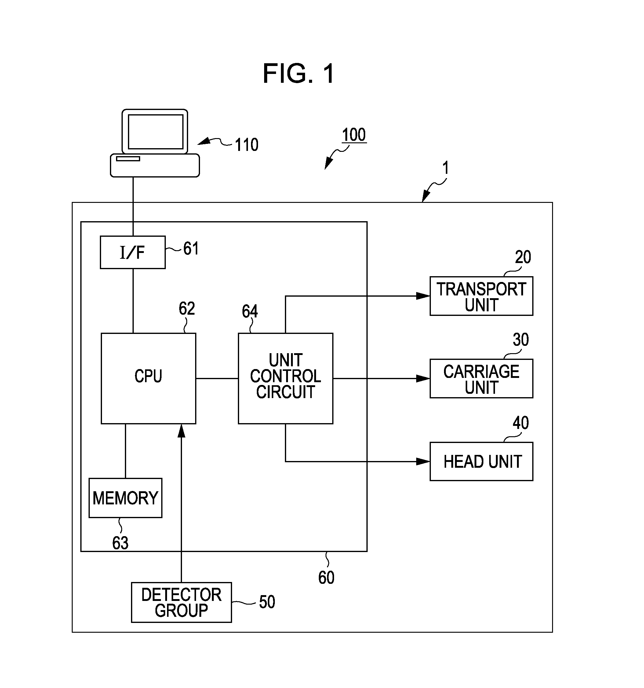
[0041]FIG. 1 is a block diagram illustrating an overall configuration of a printing system 100.
[0042]As shown in FIG. 1, the printing system 100 includes a computer 110, an ink jet printer 1 (hereinafter, referred to as “printer 1”) that actually prints an image under a control of the computer 110, and the like.
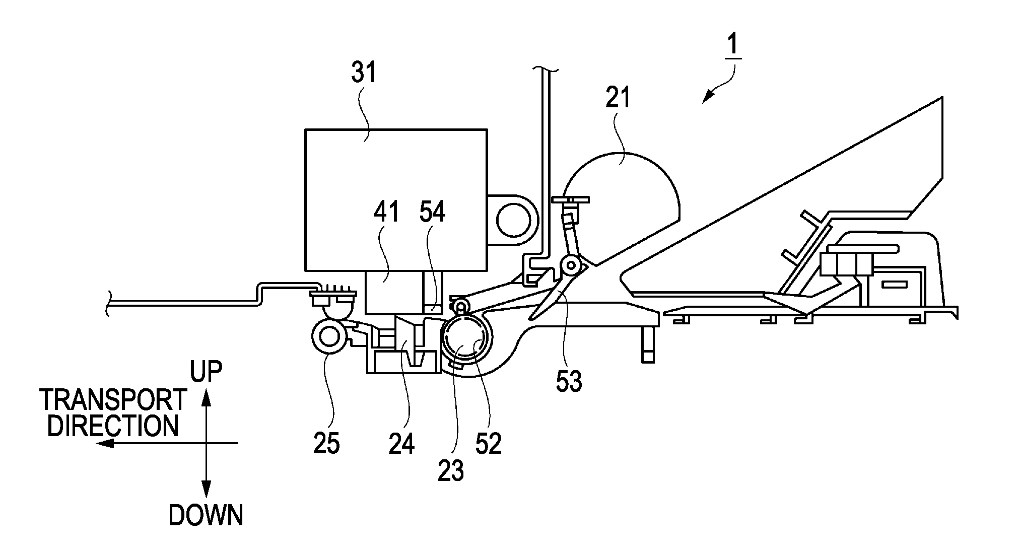
[0043]The printer 1 is a printing apparatus that forms (prints) a text or an image on a medium such as paper, cloth, film, or the like, and is communicably connected to the computer 110. In addition, a printer driver as a printing control device is installed in the computer 110. In addition, the printing system 100 integrally serves as a printing apparatus in the broad sense of the term.
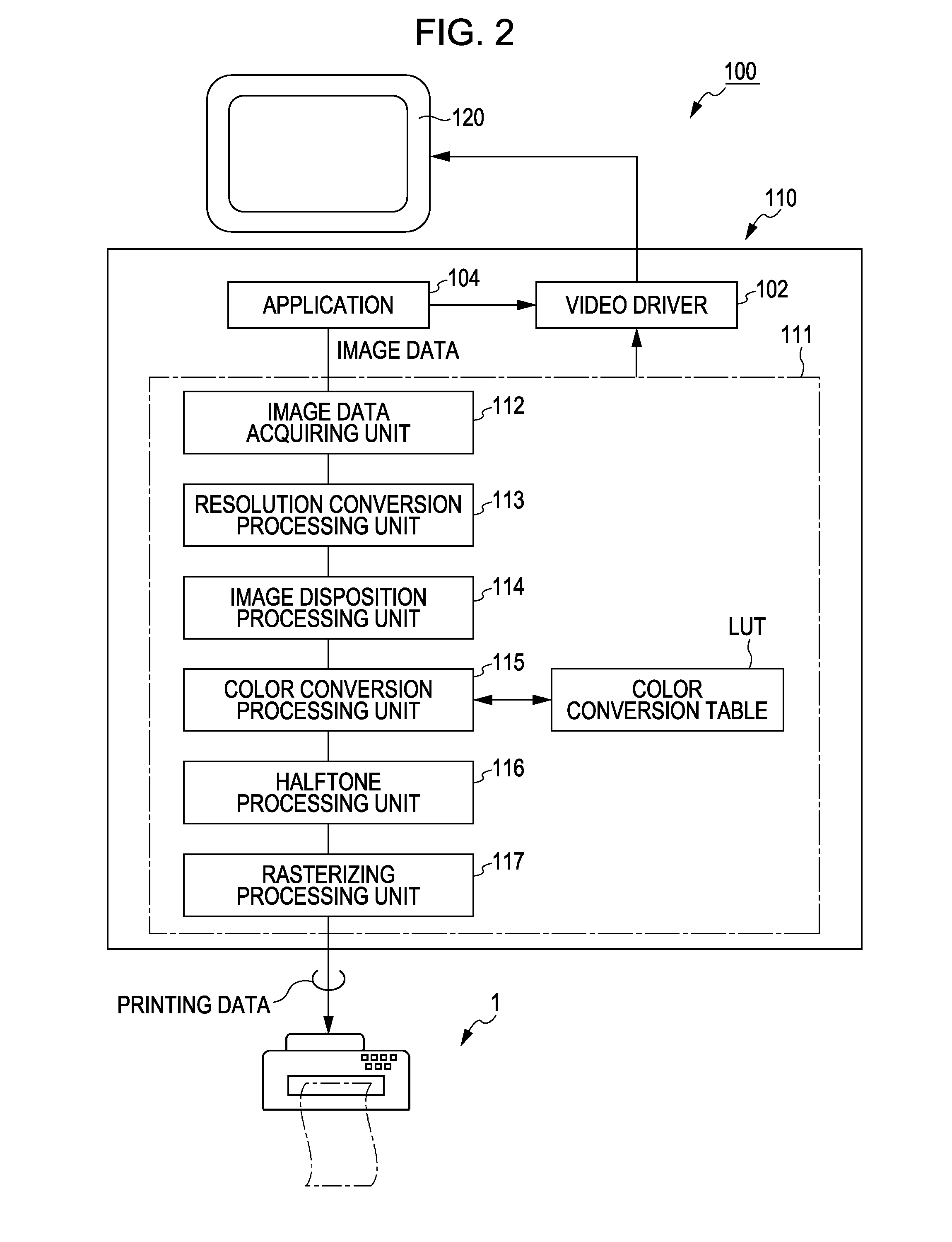
Printer Driver
[0044]Next, the printer driver in the ...
modification example 1
[0109]In FIG. 10A and FIG. 10B of the embodiment described above, the example of disposing the metallic image in the outline area RA on the outside and the inside of the outline R1 of the image is described. In this case, the outline area RA is set such that the line width of the metallic image disposed in the outline area RA is substantially the same as the line width of the metallic image disposed in the inside of the outline area RA, that is, the area surrounded with the outline area RA. However, the invention is not limited thereto, the line width of the outline area RA may be further broadened to be thicker than the line width of the color image or the metallic image disposed on the inside of the outline area RA.
[0110]FIG. 12 is a diagram illustrating an example of further broadening the line width of the outline area RA provided on the inside of the outline R1 of the image. In FIG. 12, as compared with FIG. 10B, the line width of the metallic image disposed in the outline area...
modification example 2
[0111]In FIG. 11A and FIG. 11B of the embodiment described above, the example of the image formed of the metallic image and the color image by a unit pixel. Herein, the metallic image with the horizontal width of two pixels and the color image with the horizontal width of two pixels are alternately disposed without a gap. However, the invention is not limited thereto, and the metallic image and the color image may be alternately disposed with a gap provided therebetween.
[0112]FIG. 13A and FIG. 13B are diagrams illustrating examples in which a gap is provided between the metallic image and the color image. FIG. 13A shows disposition of the metallic image and the color image by a pixel unit. FIG. 13B shows a cross-section of XIIIB-XIIIB of FIG. 13A. In FIG. 13A and FIG. 13B, blank pixels of a horizontal width and a vertical width of one pixel are provided between the metallic image and the color image. As described above, the blank pixels of one pixel are provided, it is possible to a...
PUM
 Abstract
Description
Claims
Application Information
 - R&D
- Intellectual Property
- Life Sciences
- Materials
- Tech Scout
- Unparalleled Data Quality
- Higher Quality Content
- 60% Fewer Hallucinations
Browse by: Latest US Patents, China's latest patents, Technical Efficacy Thesaurus, Application Domain, Technology Topic, Popular Technical Reports.
© 2025 PatSnap. All rights reserved.Legal|Privacy policy|Modern Slavery Act Transparency Statement|Sitemap|About US| Contact US: help@patsnap.com