
Manipulation apparatus, and movement apparatus equipped with this manipulation apparatus

a technology of manipulation apparatus and movement apparatus, which is applied in the direction of mechanical control devices, load-engaging elements, hoisting equipments, etc., can solve the problems of affecting the operation of the operator, and the configuration of the manipulation apparatus, etc., to achieve the effect of easy handling, light weight and easy manipulation

Active Publication Date: 2013-05-02
GOGOU CO LTD
View PDF14 Cites 15 Cited by
  • Summary
  • Abstract
  • Description
  • Claims
  • Application Information

AI Technical Summary

Benefits of technology

The present invention provides a manipulation apparatus that is easy for operators to handle, can be made smaller and more precise, and can confirm the operation of a drive device used in crane movement. It also includes a movement apparatus with the manipulation apparatus.

Problems solved by technology

However, this disclosure is not exactly specific, and no text can be found that teaches or suggests a constitution that takes into account the standing positions, orientation, behavior, etc., of the operator who watches the display component and people around the operator, or a manipulation apparatus that has a compact size and improves manipulation accuracy, or the specific constitution of a movement apparatus equipped with this manipulation apparatus.
In this case, the presence of an electrical signal processor for performing the computation inevitably makes the configuration of the manipulation apparatus (and particularly the electrical circuits contained in the housing of the manipulation apparatus) correspondingly more complicated, which ends up making the housing larger and less convenient for the operator to use.

Method used


Image

  • Manipulation apparatus, and movement apparatus equipped with this manipulation apparatus
  • Manipulation apparatus, and movement apparatus equipped with this manipulation apparatus
  • Manipulation apparatus, and movement apparatus equipped with this manipulation apparatus

Examples


first embodiment

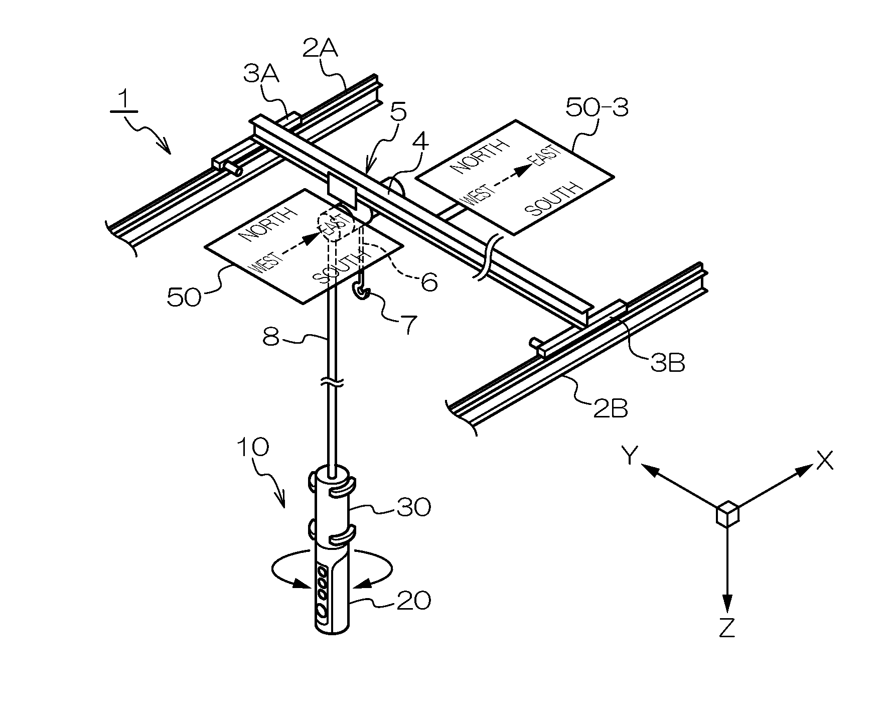
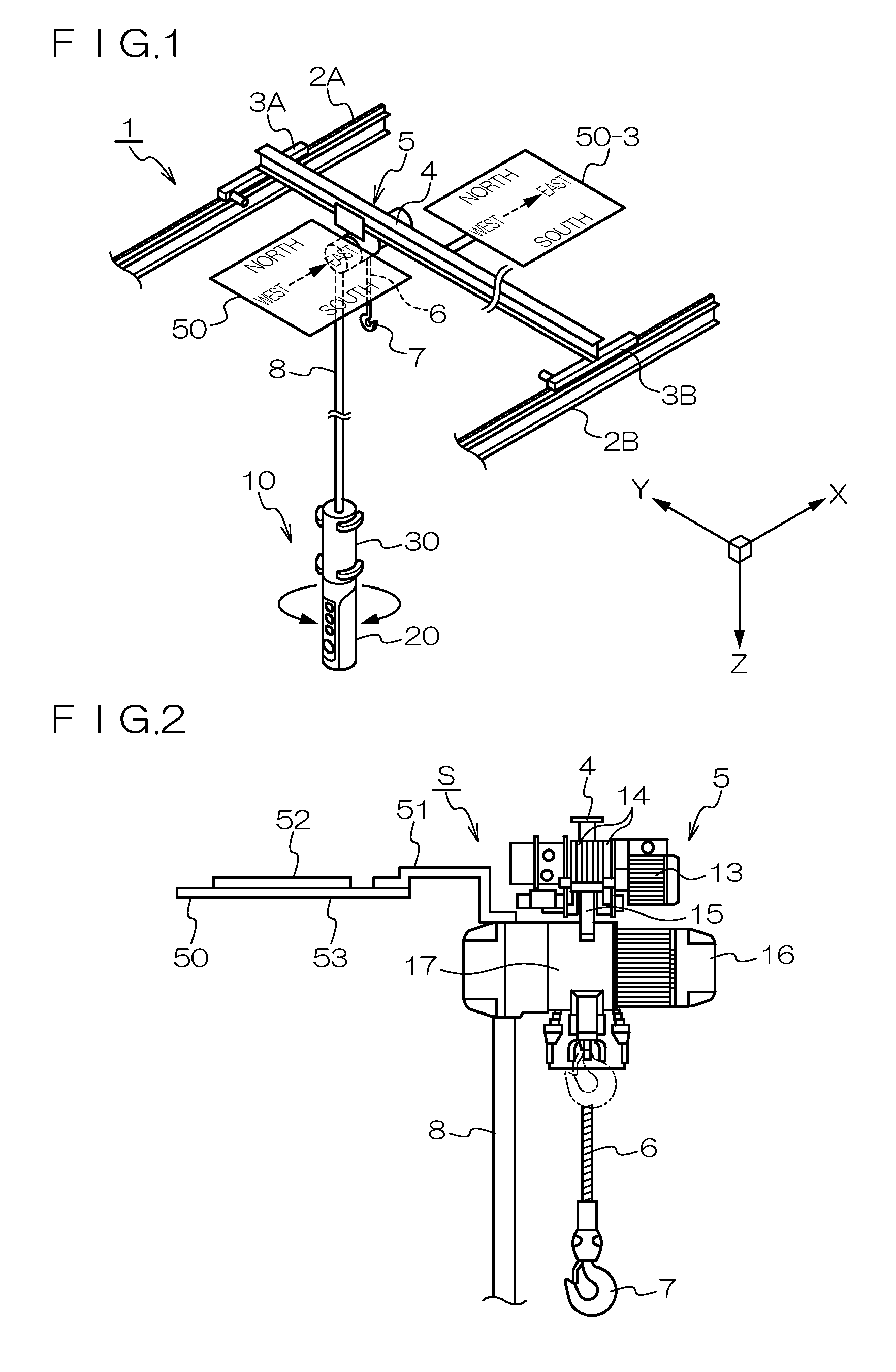
[0093]FIG. 1 is an oblique view of the overall configuration of an overhead crane serving as the movement apparatus pertaining to an embodiment of the present invention. FIG. 2 is a diagram of the structure of a winch serving as the hoist of an overhead crane serving as the movement apparatus pertaining to an embodiment of the present invention.

[0094]As shown in FIG. 1, the overhead crane 1 serving as the movement apparatus pertaining to this embodiment has at least a pair of trolley rails 2A and 2B, which are X direction rails, disposed parallel to the X direction with a specific gap between them, near the ceiling of a building. A pair of saddle rails 3A and 3B that travel in the X direction are in contact by wheels with these X direction rails 2A and 2B, respectively. A crane girder 4, which is a Y direction rail disposed in the Y direction, perpendicular to the X direction, is provided between the saddle rails 3A and 3B. There is also a trolley 5 that moves in the Y direction alo...

second embodiment

[0193]Next, an overhead crane will be described as a movement apparatus pertaining to a second embodiment of the present invention.

[0194]The overhead crane pertaining to this second embodiment has substantially the same mechanical structure as that in FIGS. 1 and 2, and its electrical structure will be described through reference to FIG. 13.

[0195]FIG. 13 corresponds to FIG. 5, which illustrates the first embodiment, and in FIG. 13, 18 is a motor control circuit, 42 is a movement control apparatus that includes a motor control circuit and the remote control 10, the display component 50 (discussed below), the communication cable 8, and so forth, and 45 is a movement mechanism. In FIG. 13, those components that are numbered the same as in FIG. 5 share the same constitution, and redundant descriptions will be omitted below, focusing mainly on the differences.

[0196]In the second embodiment, the manipulation apparatus 10-1 is formed as a single housing, and therefore differs from the mani...

third embodiment

[0224]FIG. 21 shows a third embodiment of an overhead crane as an example of the movement apparatus pertaining to the present invention. FIG. 22 is a partially enlarged cross section of an example of the internal configuration of the housing portion of a manipulation apparatus used favorably in the overhead crane of FIG. 21.

[0225]In these drawings, those components that are numbered the same as in FIG. 1 or 2 share the same constitution, so redundant descriptions will be omitted or quoted, and the following description will focus on the differences.

[0226]In this embodiment, as shown in FIG. 21, the second housing 30 is disposed near the ceiling and far away from the first housing 20, which is at the position of the operator.

[0227]As shown in FIG. 21, the first housing 20 and the second housing 30 are linked by the tubular component 60, into which is inserted a signal cable along a vertical turning shaft.

[0228]Specifically, when the movement apparatus is an overhead crane, the second...


PUM


Abstract

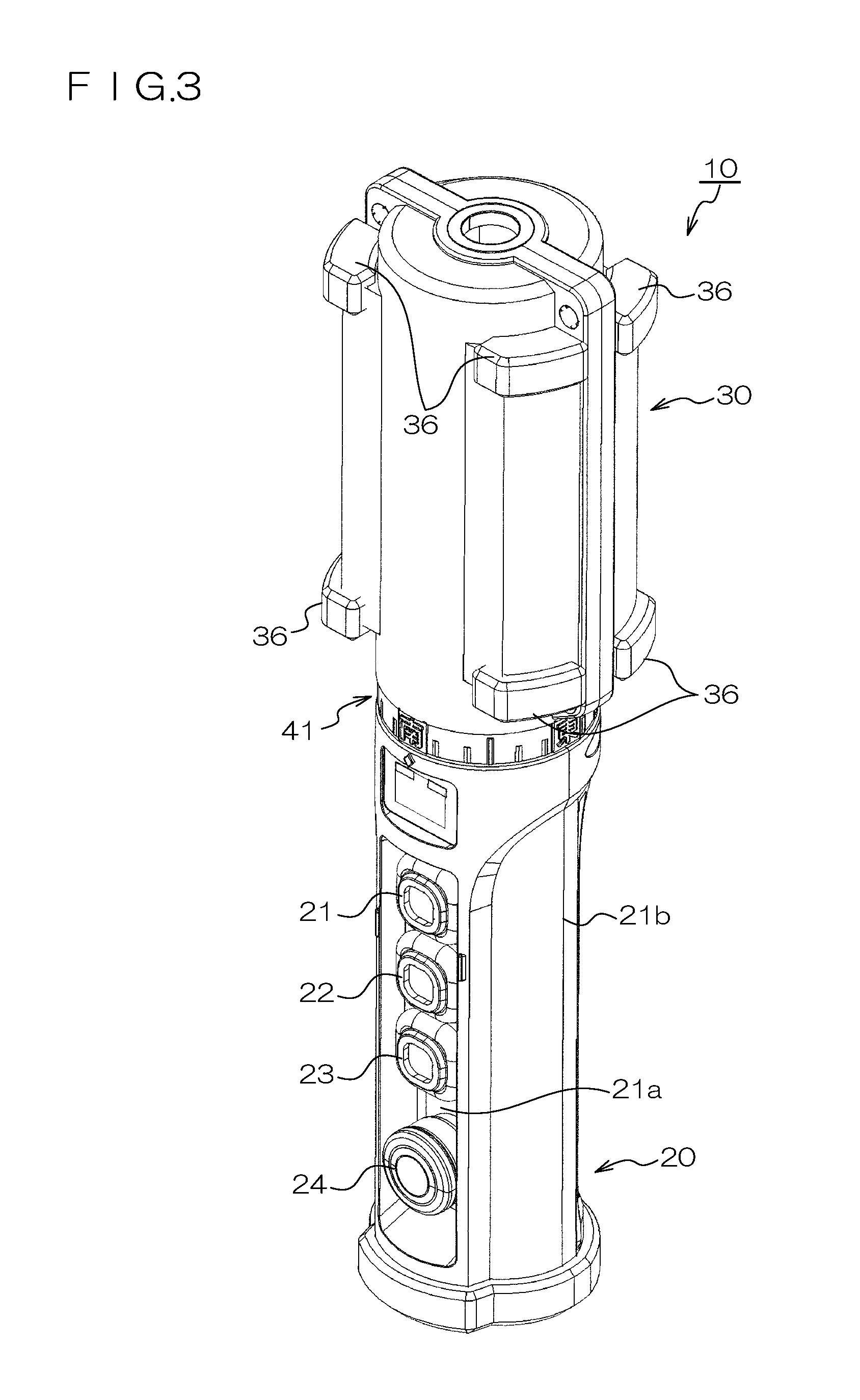
A manipulation apparatus that directs an operation of a drive device utilized in the movement of an object by changing a turning amount or reference direction of relative turning between a first housing and a second housing, wherein the first housing and second housing are in close proximity to each other along the turning axis of the relative turning, and each comprise an outer peripheral face having substantially the same diameter around the turning axis of the relative turning or having a substantially circular cross section perpendicular to the turning axis of the relative turning at this proximal position or nearby, and an indicator for indicating, in a mode that is visible by an operator, information related to the turning amount or turning direction of the relative turning is provided to each of the outer peripheral faces of the first housing and the second housing.

Description

TECHNICAL FIELD[0001]This invention relates to a manipulation apparatus with which an operator can manipulate the operation of a drive device utilized in the movement of an object, and to a movement apparatus comprising this manipulation apparatus, and more particularly relates to a manipulation apparatus with which an operator can manipulate the direction and so forth of operation of a drive device utilized in the movement of an object by changing the turning amount of relative turning between the housing of a first apparatus element and the housing of a second apparatus element, and to a movement apparatus comprising this manipulation apparatus.[0002]A person who manipulates the operation of a drive device with the manipulation apparatus in the present invention shall be referred to as an “operator.” Also, in the present invention, at least part of the people around the operator (within the range of manipulation work when the operator manipulates the manipulation apparatus, within...

Claims


Application Information

Patent Timeline
Patent Type & Authority Applications(United States)
IPC IPC(8): B66C13/18B66C13/16
CPCB66C13/40G05G1/08B66C15/065B66C13/18B66C13/16B66C3/18B66C13/44B66D3/18
Inventor OGAWA, KOUJIYAMAGUCHI, FUJIOKI
Owner GOGOU CO LTD
Learn More