
Method and system of interference cancelation in collocated transceivers configurations

Active Publication Date: 2013-04-25
UBIQAM
View PDF4 Cites 303 Cited by
  • Summary
  • Abstract
  • Description
  • Claims
  • Application Information

AI Technical Summary

Benefits of technology

The present invention relates to a method of cancelling interference in a wireless system. The method involves acquiring the interfering signal, generating an analog or digital cancellation signal based on the acquired interfering signal and injecting it into the interfered receiver to reduce the interference. The method can provide a reduced degree of freedom for beamformer weights setting and can be used to reduce interference introduced in a wireless system.

Problems solved by technology

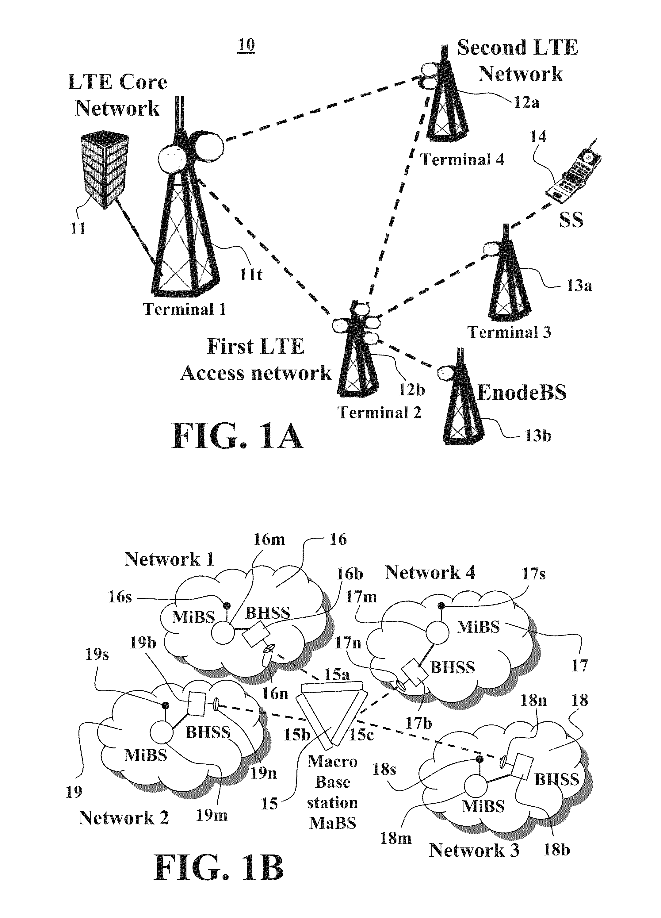
This situation causes major difficulties, as the antennas of the MiBS and BHSS are located in close proximity, where one antenna is transmitting and the other antenna is receiving, and both transceivers use the same (or close) frequency band in the same frequency block.
As a result, interferences are typically introduced in signals received in antennas of both BHSS and MiBS receivers, which hamper the quality of service (QoS) and the extent of potential capacity of both the backhaul and access links.
It is noted that such interferences also occur when the collocated transceivers are not using the same frequency channel, but are still using the same spectrum block (or band).
Thus, the strong interfering signal in the same spectrum block will hamper the communication link, which may cause saturation in the receiver's front RF stages that cannot be corrected later in the digital baseband signal processing.
Such strong interferences may enforce lower gain of the low noise amplifier (LNA) attempting to avoid saturation in the receiver front end circuit, which may hamper the whole link performances of both collocated transceivers.
Interference may be also caused by transmitter deficiencies that may result in out-of-band, or in-band, output noise.
This out-of-band, or in-band, transmitter noise may be so strong within the receiver's band such that it may hamper the desired signals.
Such interference between collocated overlapping antenna patterns typical occurs in backhaul feeder implementations, when the same frequency band is used for the communication of a plurality of SBBSs.

Method used


Image

  • Method and system of interference cancelation in collocated transceivers configurations
  • Method and system of interference cancelation in collocated transceivers configurations
  • Method and system of interference cancelation in collocated transceivers configurations

Examples


Embodiment Construction

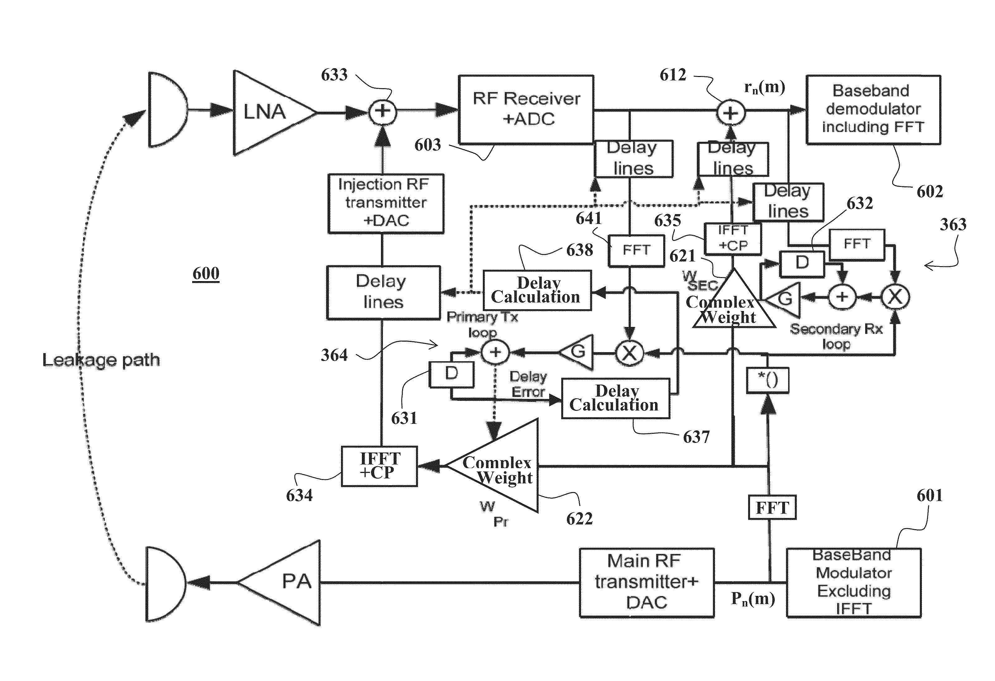
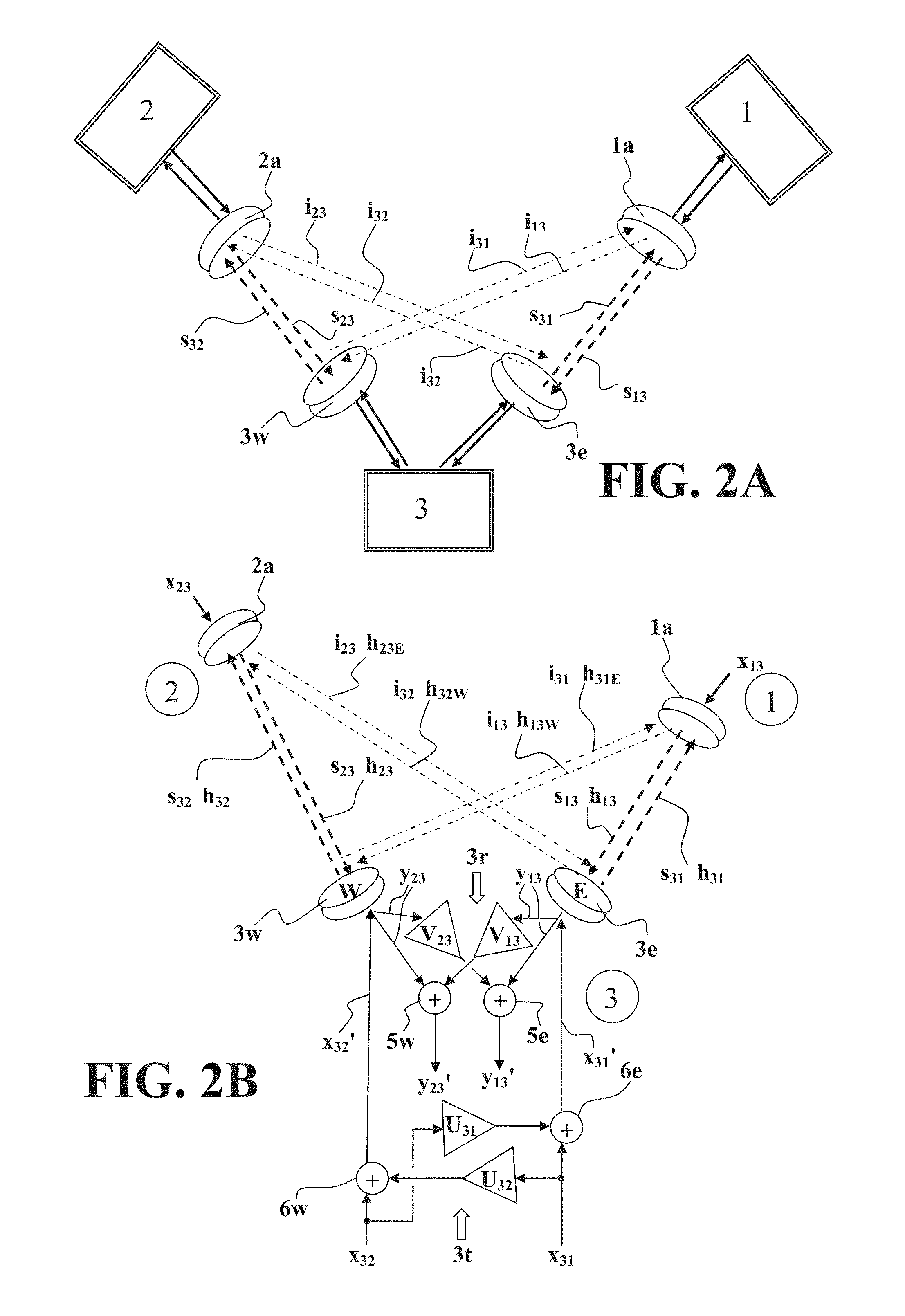
[0094]The present invention, in some embodiments thereof, relates to method and system of canceling self, adjacent channel, and / or cross-lobe interferences (e.g., interferences introduced due to overlap in antenna radiation pattern of adjacently located receiving and transmitting antennas) which typically appear when two or more proximally located antennas of collocated receivers and transmitters are operating concurrently. In general, the interference cancellation techniques of some embodiments of the present invention utilize interference cancellation loops for processing the interfering signals and generating a suitable cancellation signal to be injected in the analog and / or digital signal processing path of the interfered receiver that receives the interfered target signal.

[0095]Some exemplary embodiments of the present invention relate to configurations wherein the interfering transmitters and interfered receivers, and their antennas, are collocated (e.g., in the same hub or to...


PUM


Abstract

The present invention, in some embodiments thereof, relates to a method of cancelling interference in a wireless system, wherein the interference introduced by an interfering signal causing reception of an interfered signal responsive to transmission of a desired signal, the method comprising acquiring the interfering signal from a transmitter during or before transmission thereof, generating an analog cancellation signal based on the acquired interfering signal, and injecting said analog cancellation signal into an interfered receiver receiving said interfered signal to reduce said interference therefrom.

Description

RELATED APPLICATIONS[0001]This application claims the benefit of priority of Israeli Patent Application No. 206008 filed May 27, 2010, the disclosure of which is incorporated herein by reference in its entirety.FIELD AND BACKGROUND OF THE INVENTION[0002]The present invention, in some embodiments thereof, relates to a method and system of cancelling interferences in RF communication systems, such as, for example, self interferences occurring in collocated transceivers configurations and antennas pattern partial overlap interferences (also referred to herein as cross lobe interferences).[0003]For example, wireless networks relay base-stations (BSs) are often used to connect remote subscriber-stations (SSs) to the wireless network over a wireless backhaul link that is typically operating within the same frequency band or frequency block used by the relay BS to communicate with the SSs. The backhaul communication is carried out between the relay BS and another BS (typically a wired BS o...

Claims


Application Information

Patent Timeline
IPC IPC(8): H04B1/10
CPCH04B1/126H04B1/10H04B1/525
Inventor CYZS, BARUCHMEIR, AMIRAMIDAN, ORENMANOR, DANIEL
Owner UBIQAM
Learn More