
Fluid ejection device

a technology of ejection device and fluid, which is applied in the direction of liquid transfer device, machine/engine, laboratory glassware, etc., can solve the problems of ejection device capable of supplying liquid droplets of a few nk and may not adjust the volume of ejection fluid, and achieve the effect of improving accuracy in a fixed quantity supply

Inactive Publication Date: 2013-04-25
SAMSUNG ELECTRO MECHANICS CO LTD
View PDF6 Cites 4 Cited by
  • Summary
  • Abstract
  • Description
  • Claims
  • Application Information

AI Technical Summary

Benefits of technology

The present invention provides a fluid ejection device that can eject different volumes of fluids from a single device and measure the volume of the fluid before it is ejected. This improves accuracy in supplying a fixed quantity of fluid. The device includes an optical imaging device that can measure the volume of the first fluid ejected from the piezo pipette head or the second fluid formed on the fluid collection unit. The device also has an image inspection region that corresponds to the image of the first fluid or the second fluid to accurately measure its volume.

Problems solved by technology

Although such a fluid ejection device may adjust the amount of ejected fluid through electronic controlling, since a minimal amount of droplets supplied through the ceramic nozzle may be several tens of μl, it may be difficult to supply a fixed quantity of fluid, and to provide a fine amount of fluid.
However, the ejection device capable of supplying liquid droplets of a few nk may not adjust the volume of an ejected fluid, and types of ejection devices vary depending on the volumes of the ejected fluid.
That is, separate fluid ejection devices need to be used according to the volumes of ejected fluids, which may cause inconvenience in using fluid ejection devices as well as causing a problem in terms of cost.
In addition, fluid ejection devices need to be alternately used according to volumes of ejected fluids, increasing time required for exchanging or operating experiment devices, and the concentration of an experimenter may be degraded to cause a lowering of precision of the experiment.
Furthermore, if fluids ejected from a single fluid ejection device are different, ejection conditions may need to be inconveniently reset.

Method used


Image

  • Fluid ejection device
  • Fluid ejection device
  • Fluid ejection device

Examples


Embodiment Construction

[0033]Embodiments of the present invention will now be described in detail with reference to the accompanying drawings. However, it should be noted that the spirit of the present invention is not limited to the embodiments set forth herein and those skilled in the art and understanding the present invention can easily accomplish retrogressive inventions or other embodiments included in the spirit of the present invention by the addition, modification, and removal of components within the same spirit, but those are construed as being included in the spirit of the present invention.

[0034]Further, like reference numerals will be used to designate like components having similar functions throughout the drawings within the scope of the present invention.

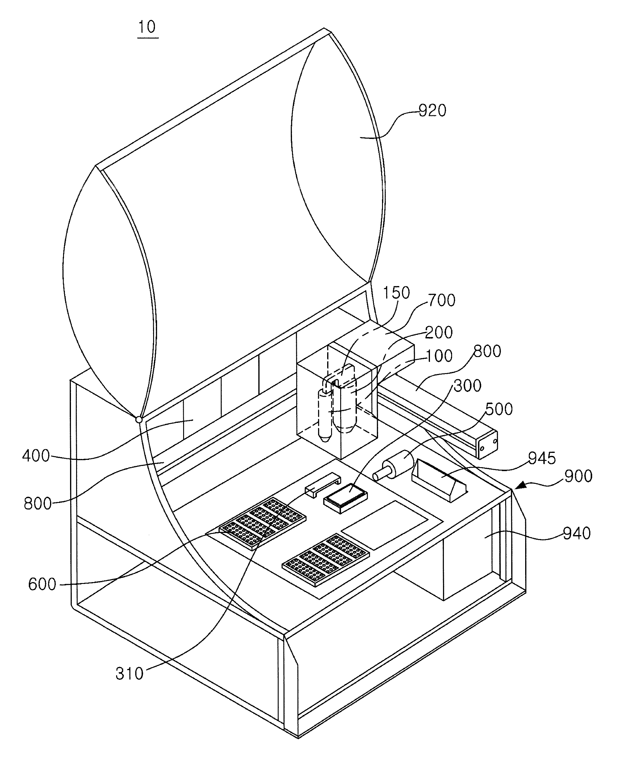
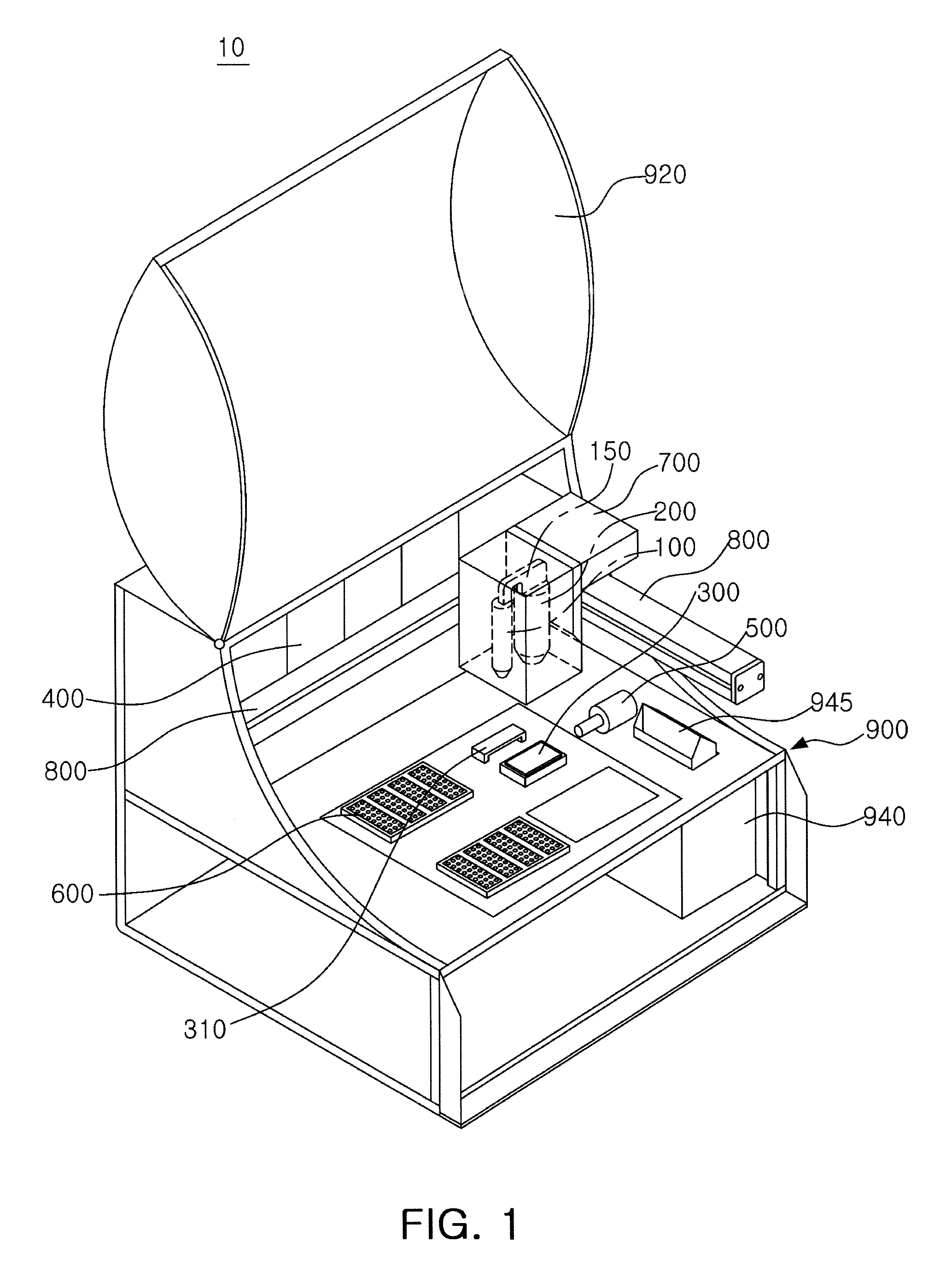
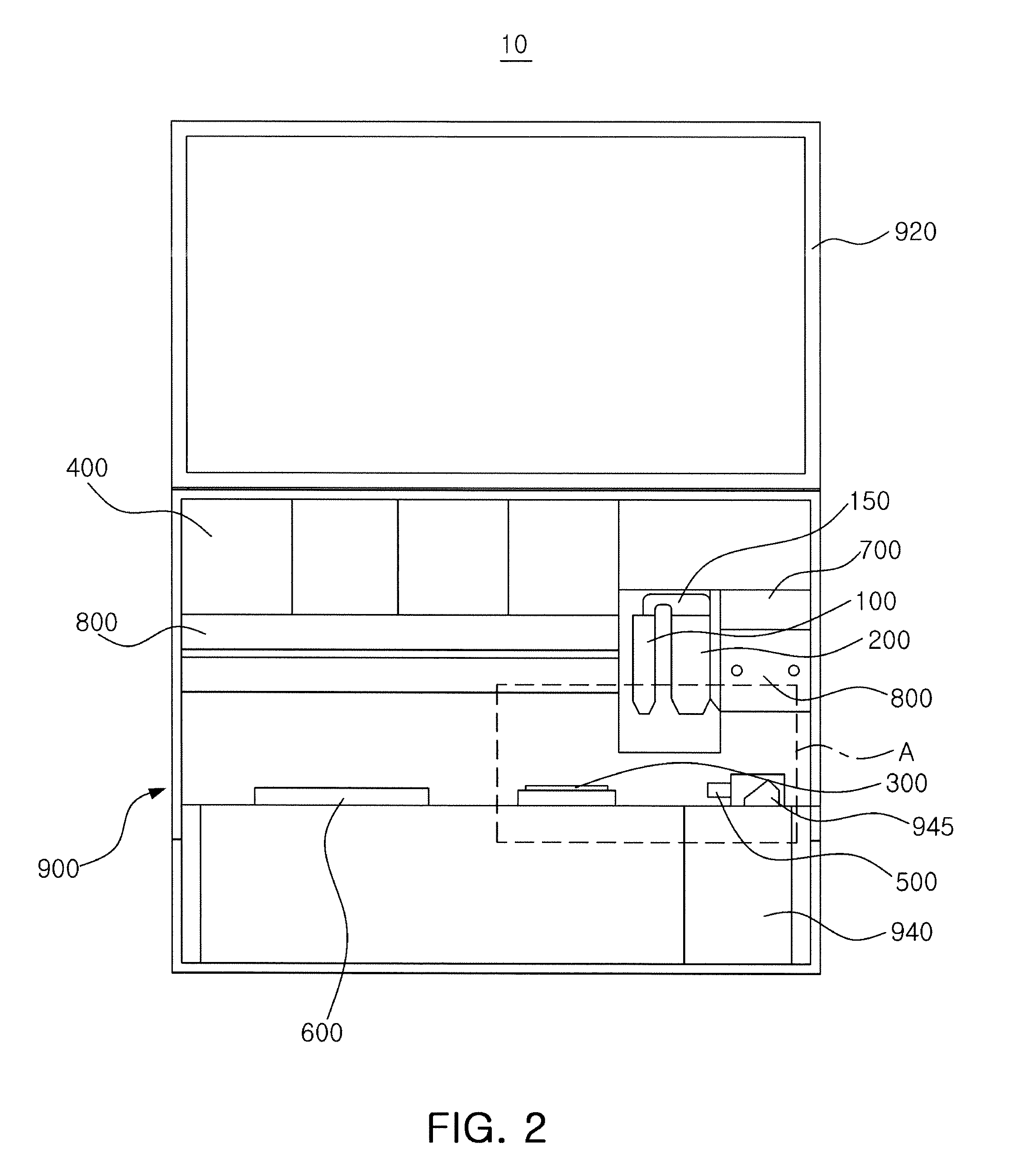
[0035]FIG. 1 is a schematic perspective view of a fluid ejection device according to an embodiment of the present invention. FIG. 2 is a schematic front view of the fluid ejection device according to the embodiment of the present inventio...


PUM


Abstract

There is provided a fluid ejection device, including a piezo pipette head ejecting a first fluid; a solenoid valve head disposed to be adjacent to the piezo pipette head and ejecting a second fluid having a volume relatively larger than that of the first fluid; and a fluid collection unit allowing the second fluid ejected from the solenoid valve head to be formed thereon to thereby allow the volume of the second fluid to be measured by an optical image device.

Description

CROSS-REFERENCE TO RELATED APPLICATIONS[0001]This application claims the priority of Korean Patent Application No. 10-2011-0109261 filed on Oct. 25, 2011, in the Korean Intellectual Property Office, the disclosure of which is incorporated herein by reference.BACKGROUND OF THE INVENTION[0002]1. Field of the Invention[0003]The present invention relates to a fluid ejection device, and more particularly to a fluid ejection device allowing various volumes of fluids to be ejected from a single device.[0004]2. Description of the Related Art[0005]In conducting research using bio-chips, it is very important to supply a fixed quantity of fluid such as a culture medium or reagent to bio-chips to determine the accuracy of experimental results.[0006]A fixed quantity supply of fluid is more important in cell chips essentially requiring a toxicity test, an anticancer drug sensitivity test, and an anticancer drug resistance test to develop new medicines.[0007]According to the related art, in supply...

Claims


Application Information

Patent Timeline
Patent Type & Authority Applications(United States)
IPC IPC(8): F02M51/00
CPCB01L3/0265B01L3/0268B01L2300/0819B01L2200/143B01L2200/026
Inventor JEON, SANG YOULSON, HEE JUKU, BO SUNG
Owner SAMSUNG ELECTRO MECHANICS CO LTD
Learn More