
Device and method of enhancing production of hydrocarbons

Inactive Publication Date: 2013-04-18
GASOLINEEUM TECH
View PDF8 Cites 4 Cited by
  • Summary
  • Abstract
  • Description
  • Claims
  • Application Information

AI Technical Summary

Benefits of technology

The present invention provides a device and method to improve the performance of gas lift valves in oil and gas wells. This device offers an alternative to traditional gas lift valves and allows for enhanced performance. It works by injecting gas into the well and utilizing a valve system to create a suction pressure in the well fluid, which then pushes it up the well. The device has an invention design that increases the mixing of gas and fluid, resulting in a larger area of inflow and increased pressure for introduction into the production tubing. It also allows for easier inflow of fluids and stream line flow from the device. This device can be used in vertical or horizontal wells and can enhance the incorporation of injected fluid in the flow.

Problems solved by technology

There are some oil wells where the natural flow of hydrocarbons to the surface is not sufficient to permit or maintain commercial production.
One problem associated with such injections is that gas is a relative low density fluid compared with the fluids normally in the production tubing.

Method used


Image

  • Device and method of enhancing production of hydrocarbons
  • Device and method of enhancing production of hydrocarbons
  • Device and method of enhancing production of hydrocarbons

Examples


Embodiment Construction

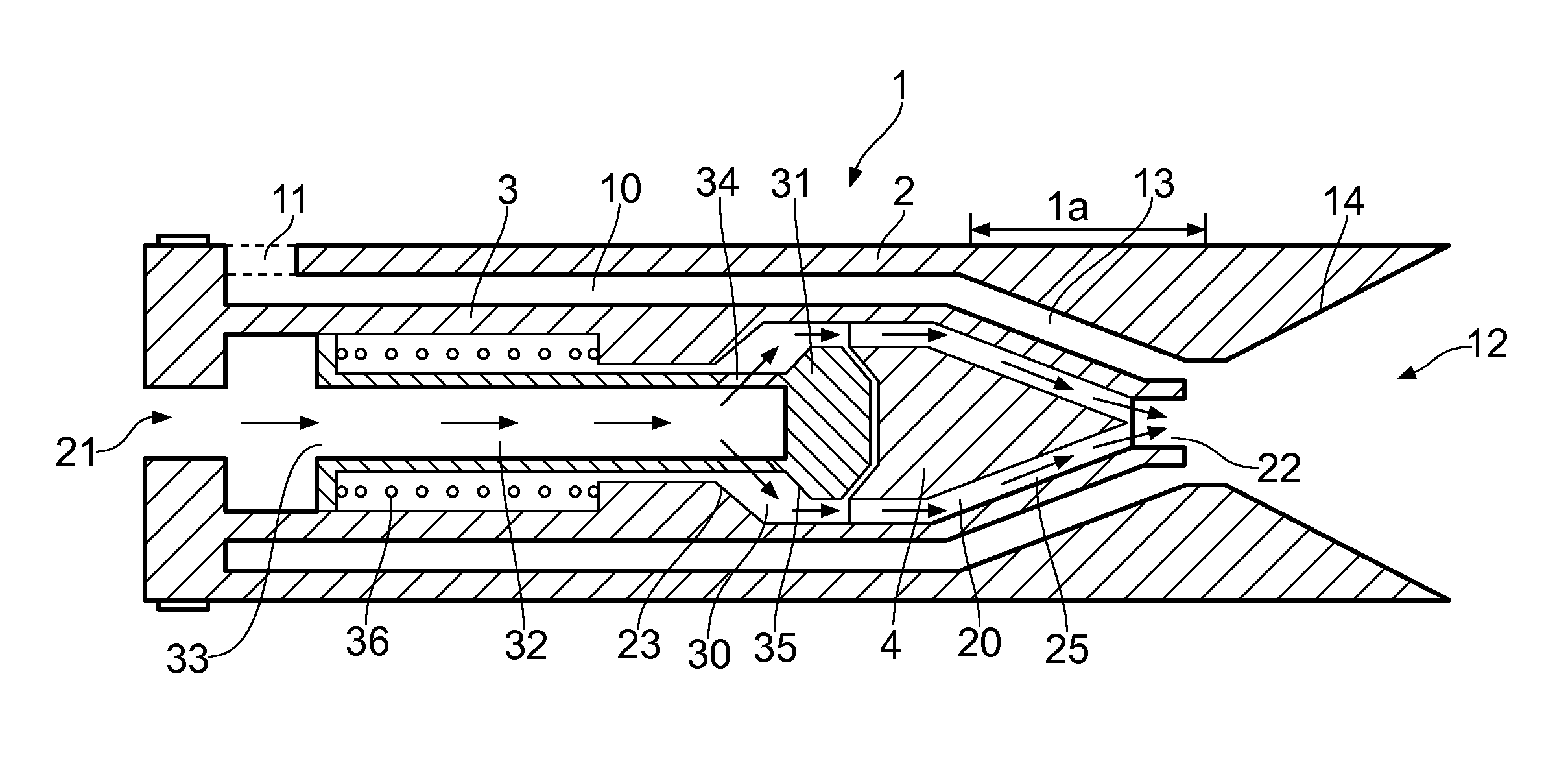
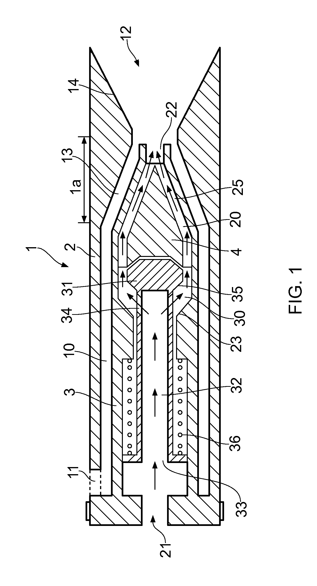
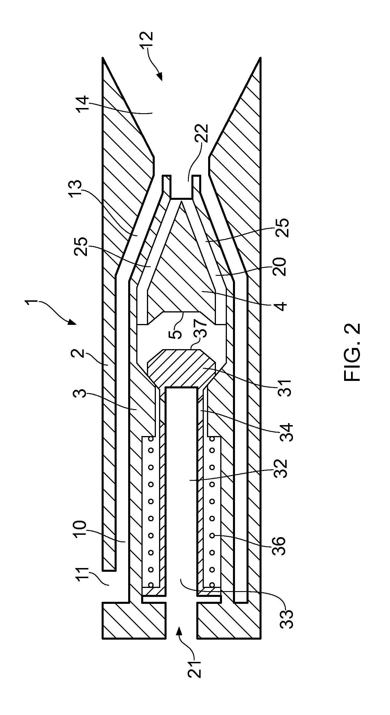
[0036]In FIGS. 1 and 2 there is shown a first embodiment where a valve device 30 in a second passage 20 of the device is shown in an open position (FIG. 1) and a closed position (FIG. 2).

[0037]The device comprises an outer housing 1 where through there is arranged two flow passages 10,20. The first flow passage 10 extends from an inlet 11 in the wall of the outer housing 1 and along the housing 1 to an outlet 12 at an end of the housing 1. The second flow passage 20 extends from an inlet 21 at an end of the housing 1 which is opposite to the outlet 12, to an internal outlet 22, positioned within the housing 1 and which leads into the first flow passage 10. This gives that the outlet 12 is a common outlet from the device for the two passages 10,20. The outer housing 1 comprises an outer sleeve element 2 and within this an internal sleeve element 3 and within this sleeve element 3 an internal block element 4, all forming parts of the outer housing 1 and fixed relative each other. The ...


PUM


Abstract

A device and an associated method, of enhancing production of hydrocarbons from a wellbore by the use of a device, where the device is arranged in a side pocket mandrel. The method, and associated device, includes means for allowing a fraction of a main production flow to enter a first flow passage (10) in the device through an inlet (11) and to mix with the fluid from a second flow passage (20) in the device, before returning the mixed flow to the main production flow.

Description

FIELD OF THE INVENTION[0001]The present invention relates to a device and a method of use in a wellbore for oil and or gas production from a formation, preferably in relation to gas injection as a gas lift valve.BACKGROUND[0002]There are some oil wells where the natural flow of hydrocarbons to the surface is not sufficient to permit or maintain commercial production. This may be due, for example, to the hydrocarbons' viscosity and / or weight, or the fact that the pressure in the oil well is too low to counteract the hydrostatic pressure of the fluid in the well together with the counter-pressure exerted on the fluid in the oil well by the processing installations.[0003]For such oil wells a number of systems and different principles have therefore been developed which can increase the oil well's production by means of so-called artificial lifting. The two most commonly used systems today are water injection and gas injection. With gas injection natural gas under high pressure is injec...

Claims


Application Information

Patent Timeline
IPC IPC(8): F04F5/00
CPCF04F5/00E21B43/123
Inventor STOKKA, OYVINDTVEITEN, MAGNARPETTERSEN, STALEKLEPPA, ERLING
Owner GASOLINEEUM TECH
Learn More