LED lamp
a technology of led lamps and led sockets, applied in the field of lighting, to achieve the effect of improving safety
- Summary
- Abstract
- Description
- Claims
- Application Information
AI Technical Summary
Benefits of technology
Problems solved by technology
Method used
Image
Examples
second embodiment
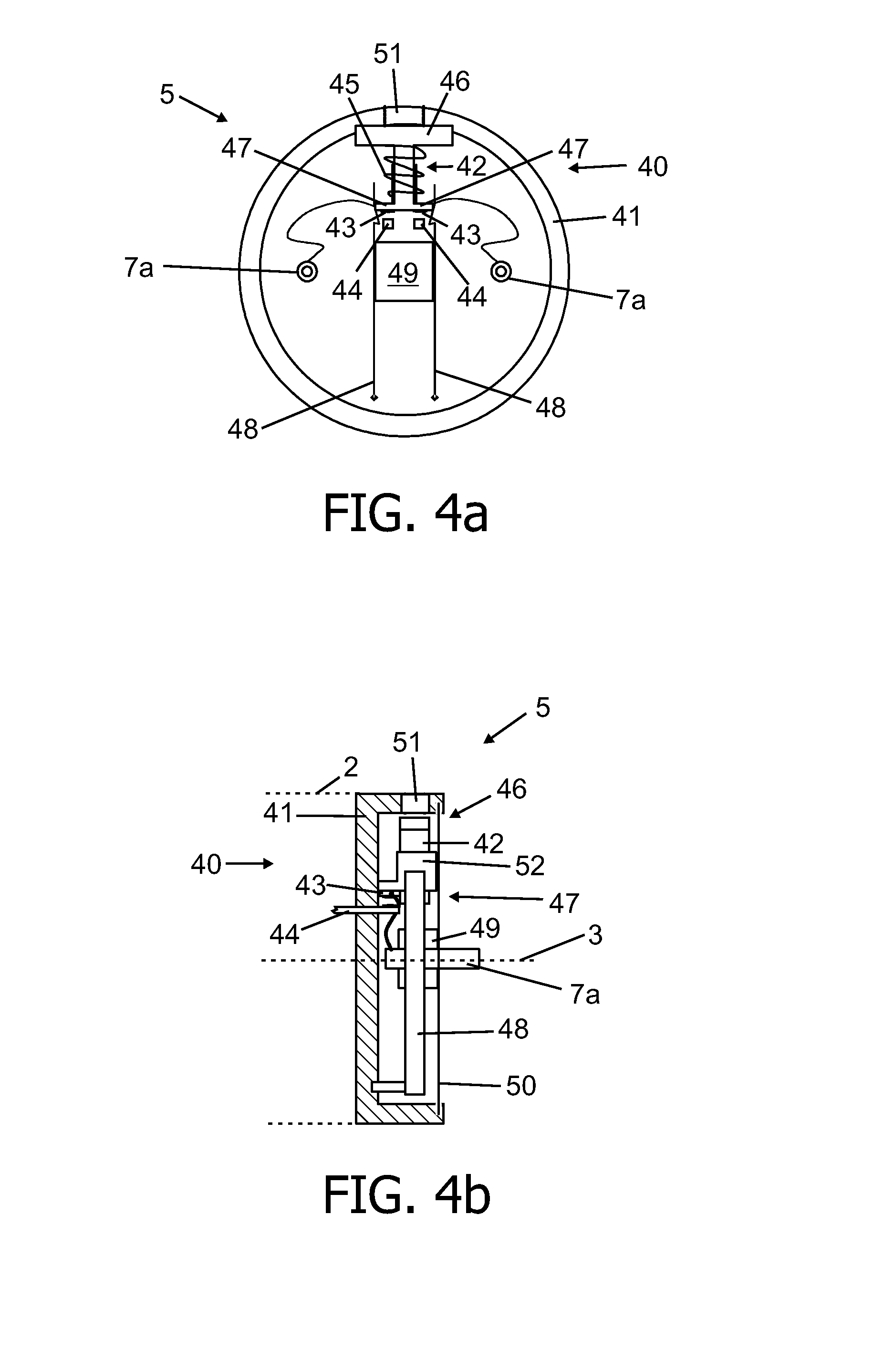
[0085]FIG. 7-9 show a first lamp cap 5′ of a LED lamp 1. The present embodiment corresponds substantially to the embodiment of FIG. 4-6 with the exception of a modified release base plate 50′, which provides a safe disconnection of the contact pins 7a from the LED unit 4 also in case the LED lamp 1 is mounted to a “linear-type” fixture (not shown). Here, the contact pins 7 are installed to or deinstalled from the slots, formed in the sockets of such fixture by a linear drawing movement.
[0086]Typically, the contact pins 7 are clamped in the operating position in the sockets 23, 24 by contact-springs to safely hold the lamp.
[0087]As can be seen in particular from the views of FIGS. 7a and 7b, which show the switching members 42 in the connected state, the two contact pins 7a and the release element 49′ are fixed to a linear mount 70, which is connected with the base plate 50′. The linear mount 70 is movable against the base plate 50′ along axis 73, perpendicular to the lamp axis 3. Th...
third embodiment
[0091]FIGS. 10a and 10b show a lamp cap 5″ of an LED lamp 1 which is shown according to the side view of e.g. FIG. 4b. While FIG. 10a shows the switching member 42′ in the disconnected state, FIG. 10b shows the switching member 42′ in the connected state.
[0092]The present embodiment corresponds substantially to the embodiment of FIG. 7-9, however, in contrast to the above embodiment, the safety switching arrangement 40′ and in particular the switching member 42′ comprises a contact arm 100, extending through an elongate opening (not shown) in the cap housing 41′ into the housing 2 of the lamp 1. The contact arm 100 holds first contacts 43, connected to the LED unit 4 (not shown). The two contact pins 7a according to the present embodiment are connected to second contacts 44. Although the side views of FIGS. 10a and 10b only show one pair of the first 43 and second contacts 44, the arrangement of the other pair of contacts 43 and 44 corresponds to the shown setup. The operation of th...
fourth embodiment
[0093]a lamp cap 5′″ is shown in FIGS. 11a and 11b according to the side view of e.g. FIG. 4b. The present embodiment corresponds substantially to the embodiment of FIGS. 10a and 10b. However, the contact arm 100 according to the present embodiment comprises a permanent magnet 104. The contact pins 7a are connected to the LED unit 4 (not shown) using reed switches 105.
[0094]FIG. 11a shows the switching member 42″ in the disconnected state. The reed switches 105 are in an open position. When the switching member 42″ is set to the connected state, as shown in FIG. 11b, the movement of the switching member 42″ accordingly shifts the permanent magnet 104 in the vicinity of the reed switches 105, which upon the presence of a magnetic field of a sufficient magnitude, connect the contact pins 7a with the LED unit 4.
[0095]The invention has been illustrated and described in detail in the drawings and the foregoing description. Such illustration and description are to be considered illustrati...
PUM
 Abstract
Description
Claims
Application Information
 - R&D
- Intellectual Property
- Life Sciences
- Materials
- Tech Scout
- Unparalleled Data Quality
- Higher Quality Content
- 60% Fewer Hallucinations
Browse by: Latest US Patents, China's latest patents, Technical Efficacy Thesaurus, Application Domain, Technology Topic, Popular Technical Reports.
© 2025 PatSnap. All rights reserved.Legal|Privacy policy|Modern Slavery Act Transparency Statement|Sitemap|About US| Contact US: help@patsnap.com


