
Position sensing head with redundancy

Active Publication Date: 2013-04-11
NYCE DAVID SCOTT +1
View PDF12 Cites 2 Cited by
  • Summary
  • Abstract
  • Description
  • Claims
  • Application Information

AI Technical Summary

Benefits of technology

The technology described in this patent uses a simplified electronics module with a sensing element and a resonant circuit to provide a high-temperature, variable frequency output signal. This allows for high-temperature operation and the use of components that can be found on the market with operating temperatures of 225°C or more. The amplitude of the output signal is not indicative of the signal, even with a separation distance of more than 10 meters between the sensing head and a receiving device, ensuring accuracy of the signal. The use of the simplified electronics module also enables the sourcing of components that can operate in environments of higher levels of ionizing radiation. In summary, this technology simplifies and advances the design of position sensors with improved accuracy and reliability.

Problems solved by technology

The included analog and / or digital circuits for powering and signal conditioning are generally somewhat complex, and the required specialized components are difficult or impossible to find on the market with maximum temperature capability of more than 125° C.
This places limitations on the length (a few inches) and type of cable (individually shielded pairs), and requires a specialized electronics module that is designed for the type of sensing element and that is calibrated for exactly that particular magnetostrictive sensor.
This mechanical coupling introduces errors due to differences in alignment, free-play, and other imperfect attributes of the mechanical couplings.
But, having a movable coil and electronics assembly, this arrangement is not suitable for separation of the sensing element from the electronics module.

Method used


Image

  • Position sensing head with redundancy
  • Position sensing head with redundancy
  • Position sensing head with redundancy

Examples


Embodiment Construction

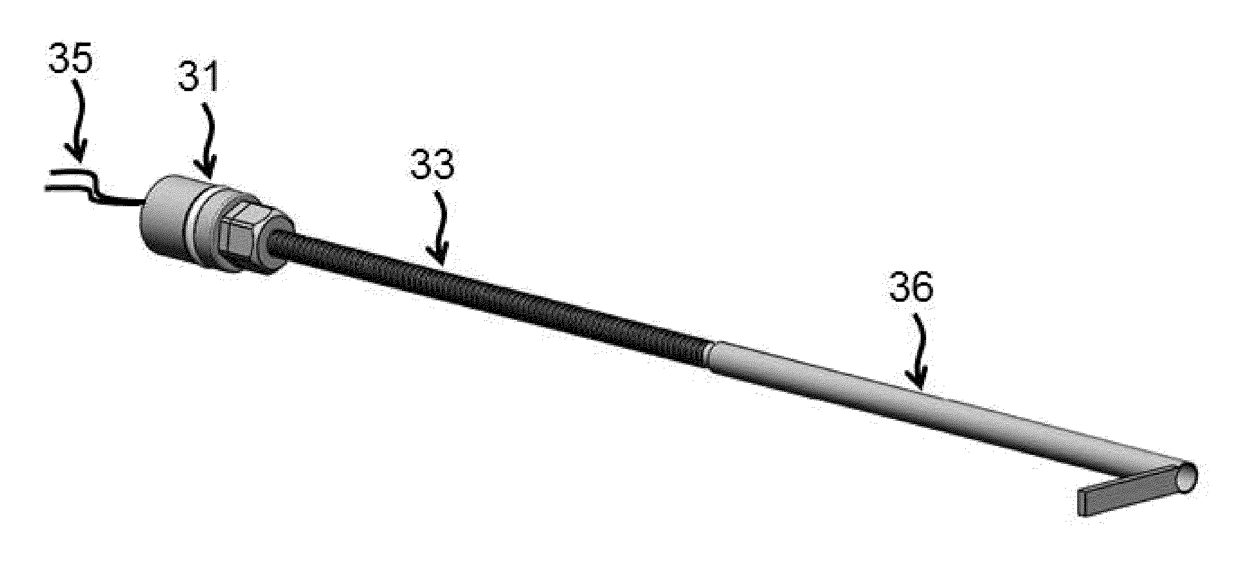
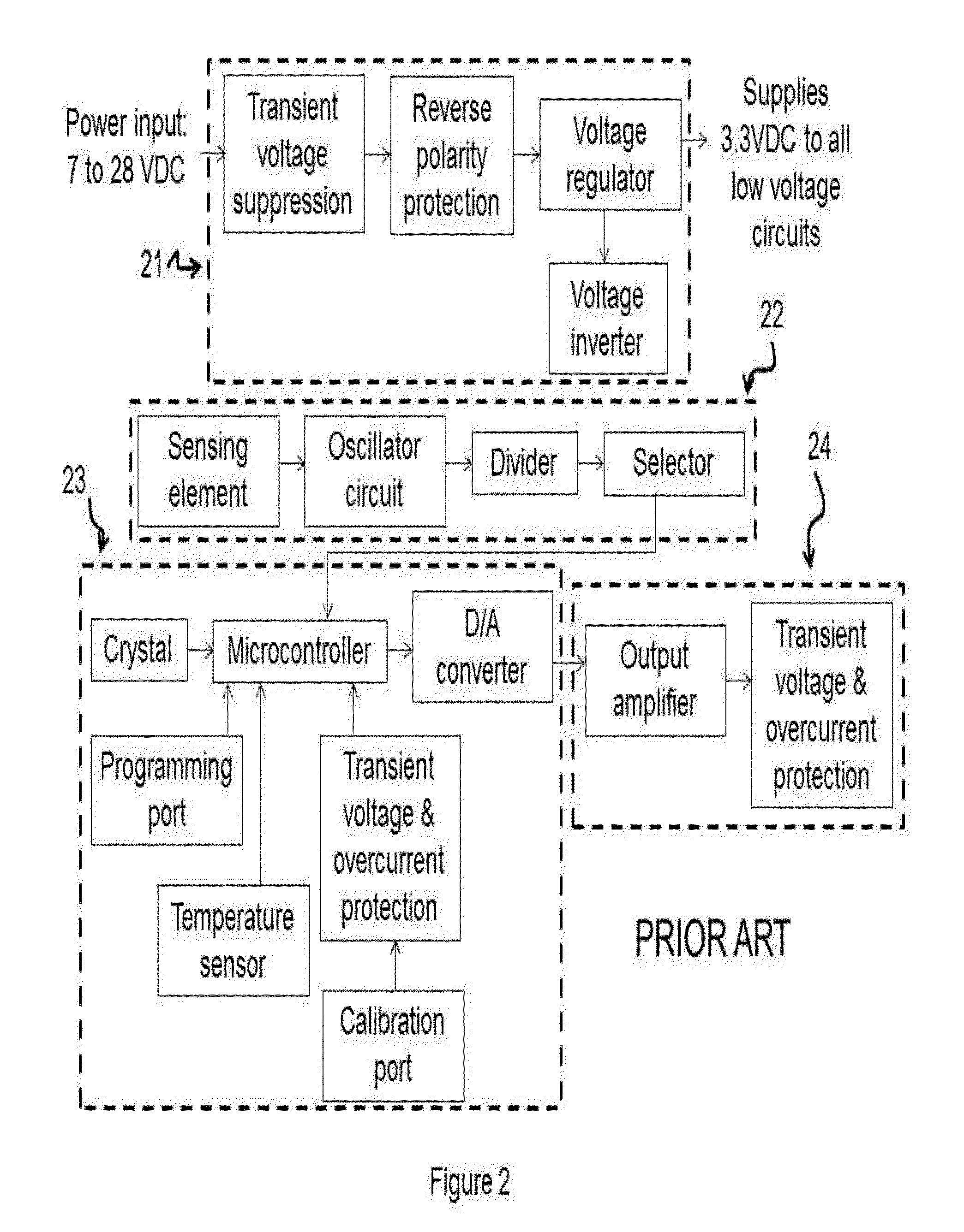
[0025]In order to implement the first improvement of the invention, which is a sensing head, a simplified circuit is designed so that, if desired, only basic electronic components of the type that are easily found on the market with operating temperatures of 225° C. and higher may be used. The simplified circuit includes an oscillator coupled with a sensing element. The sensing element can be of a new design, or one that is already known in the art. The sensing element and oscillator provide a frequency that is representative of a measured position. The simplified circuit also includes a buffer to output the signal frequency. The combination of one or more oscillators and one or more buffers comprises the simplified electronic module.

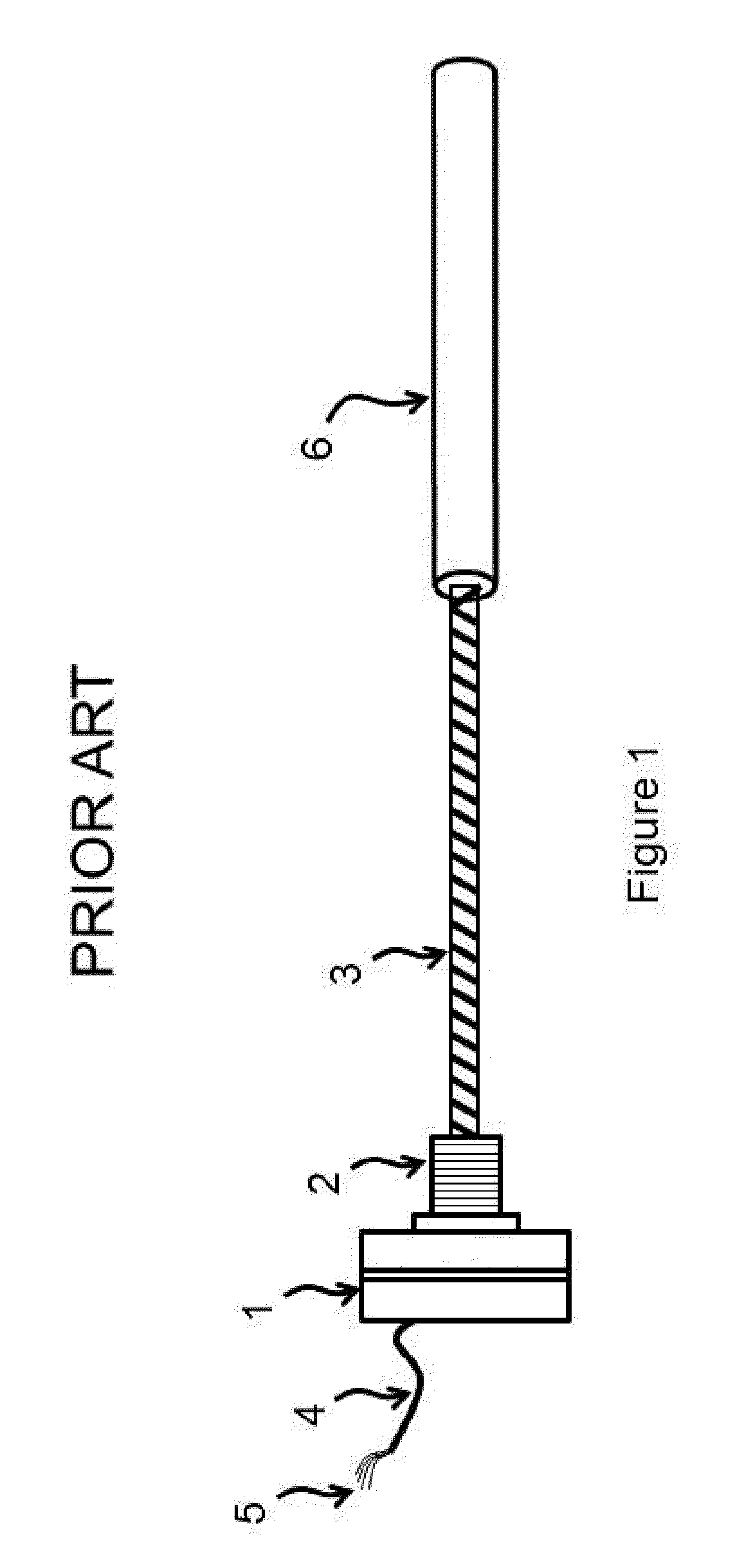
[0026]FIG. 1 is a Prior Art electromagnetic linear position sensor in accordance with U.S. Pat. No. 7,216,054. The housing (1) encloses an electronics module (not shown), which is usually manufactured as a printed circuit board having electronics compon...


PUM


Abstract

A position sensing head combines a sensing element and a simplified electronic module to enable operation with one wire, in addition to a circuit common, for providing power and transmitting a signal, while separating the sensing head from signal conditioning circuits by over 10 meters. The simplicity of the electronic module allows the use of basic electronic components that operate at more than 225° C. The signal is a variable frequency impressed onto the one wire, which can be read by a frequency meter. Another signal, such as a position or temperature, can be impressed onto the one wire at the same time as the first signal. The second signal is of a different frequency range so that it will not interfere with the first. A demodulator circuit can separate the two signals. The sensing element construction allows for locating up to three active elements measuring the same target.

Description

BACKGROUND OF THE INVENTION[0001]1. Field of the Invention[0002]The present invention relates to sensors that utilize a sensing element and electronic circuits in performing a sensing function to measure the value of a physical parameter, such as linear or rotary position, and that provide an electrical output indicative of the value of the measured parameter. Further, the present invention relates to sensors operating in an environment in which it is desirable to avoid the use of ferromagnetic materials, to minimize the physical size of the sensor, or in which a high temperature or other harsh environmental condition, such as ionizing radiation, may exist. Still further, the present invention also relates to high reliability measurements in which multiple sensors may be deployed in order to provide redundant measurements, or to sensor installations in which it is desired to connect a minimum number of wires to the sensor.[0003]2. Description of the Prior Art[0004]Prior Art sensors,...

Claims


Application Information

Patent Timeline
IPC IPC(8): G01R27/28
CPCG01D5/2291
Inventor NYCE, DAVID SCOTTGOLDMAN, LEONARD HILLEL
Owner NYCE DAVID SCOTT
Learn More