
Office Robot System

a robot and system technology, applied in the field of robot systems, can solve the problems of affecting the actuation rate of the robot actuator, the complexity of image processing, and the quality of the image transferred from the robot to the tele-operators' computers, so as to reduce capex and opex, cost-effective, and cost-effective

Inactive Publication Date: 2013-04-04
FUNG HEI TAO
View PDF7 Cites 11 Cited by
  • Summary
  • Abstract
  • Description
  • Claims
  • Application Information

AI Technical Summary

Benefits of technology

This invention is a system that allows various office robots to be deployed, controlled and managed in a cost-effective way. It uses a computing cluster to offload the robots from processing tasks, reducing the cost of each robot. The robots can be built as low-spec mobile computing devices, and software can be upgraded over time without requiring constant robot replacement. The computing cluster centralizes management and collaboration among the robots, saving money on human intervention. It also allows for on-demand addition of computing power and memory capacity to the cluster, making it more manageable and economical. Overall, this invention provides a cost-effective solution for robotic automation in offices.

Problems solved by technology

Firstly, the many robots in the system can be built as low processing power and memory capacity mobile computing devices.
Secondly, there may be multiple versions of the robots, even of the same model, as technology is advanced along the years.
Thirdly, the computing cluster centralizes the management and administration of the robots.
The latency and bandwidth of the communications between the robots and the computing cluster may affect the image processing complexity.
The latency and bandwidth of the communications between the robots and the tele-operators' computers may affect the actuation rates of robot actuators and the quality of the images transferred from the robots to the tele-operators' computers.

Method used


Image

  • Office Robot System
  • Office Robot System
  • Office Robot System

Examples


Embodiment Construction

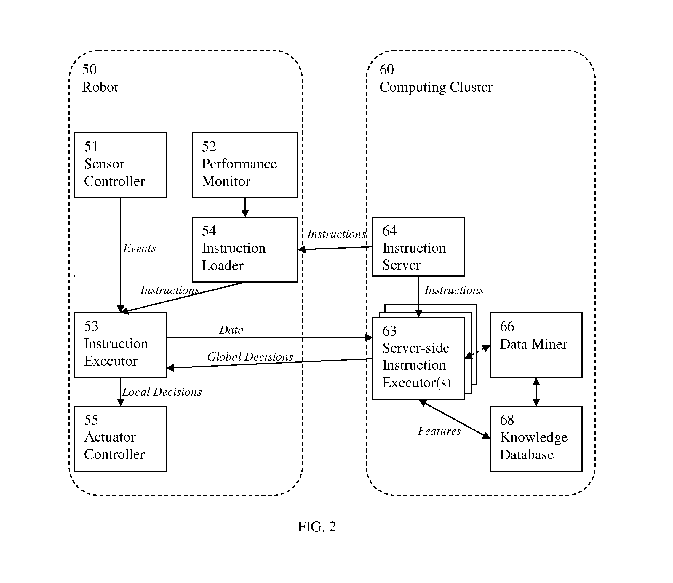
[0013]This invention is expected to be deployed in a corporate environment similar to one depicted in FIG. 1. The corporation may have one or more branch offices 10 in addition to its main office 20. Inside those branch and main offices, some autonomous and semi-autonomous robots 26 may be deployed, e.g., for handling office chores. Those robots 26 are connected to the corporate networking infrastructure, through wireless LAN or wired LAN and are capable of communicating to the computing cluster 24 via the corporate networking infrastructure. If some of those robots are to attain high level of mobility, then using wireless technology would make more sense. Typically, a branch office 10 is connected to the main office 20 through secure connections over the Internet 30. The main office 20 may have direct access to a corporate computing infrastructure 25, typically including data storage and computing servers.

[0014]The computing cluster 24 in this invention comprises a set of computers...


PUM


Abstract

An office robot system aiming at reducing both capital expenditure and operational expenditure in deploying various office robots to perform office works and functionalities is disclosed. The office robot system uses a distributed processing computing cluster, centralizing the heavy-duty robot system software computation and robot management function on the computing cluster, enables various office robots to be light-duty mobile computing devices, hence minimizing their computation and memory requirements, and enables the communications between the office robots and the computing cluster via proper corporate networking infrastructure. The office robot system facilitates deployment of heterogeneous robots with various computation capabilities. The robot system software stack is organized into layers of functional modules. Based on the computation load capable on a robot and the networking infrastructure capacity, the robot and the computing cluster divide the computation load.

Description

FIELD OF THE INVENTION[0001]The present invention relates to a system of robots for office use.BACKGROUND[0002]There have been various publications about office robots. Office robots, as the name may suggest, perform jobs in the office environment. Autonomous office robots may be used as visitor guides and for running errands, promoting products, cleaning, etc. There are also semi-autonomous office robots that facilitate worker interaction via video-conferencing; in that case, tele-operators may remotely control the office robots to look for and interact with co-workers in offices. At the technical level, the office jobs described may require the robots to be capable of recognizing some people, communicating with the people, locating the people, moving from place to place in the office while avoiding obstacles, and collaborating with other robots. While prior-art inventions focus on capability of an individual robot, such as its artificial intelligence, its electro-mechanical design...

Claims


Application Information

Patent Timeline
Patent Type & Authority Applications(United States)
IPC IPC(8): G06F19/00
CPCB25J11/003B25J13/006B25J11/0005
Inventor FUNG, HEI TAO
Owner FUNG HEI TAO
Learn More