
Device and method for detecting crowbar circuit in wind turbine

a technology of wind turbines and circuits, applied in power supply testing, program control, instruments, etc., can solve the problems of insufficient balance between input power and output power of converters, inability to simply ignore the influence of the increased installed wind power capacity on the electrical grid, and limited curren

Active Publication Date: 2013-03-28
DELTA ELECTRONICS SHANGHAI CO LTD
View PDF14 Cites 7 Cited by
  • Summary
  • Abstract
  • Description
  • Claims
  • Application Information

AI Technical Summary

Benefits of technology

The patent describes a device and method for detecting a circuit called a crowbar in a wind turbine. This device helps to quickly determine if the crowbar is working properly or if it needs to be removed. This helps to prevent damage to the wind power system and ensures that the wind turbine runs efficiently.

Problems solved by technology

However, with continuously increasing of the installed wind power capacity, after grid-connected power generation is implemented, the influence of the increased installed wind power capacity on the electrical grid cannot be simply ignored any more.
In general, the main circuit of the converter is often formed from a power semiconductor device such as an insulated gate bipolar transistors (IGBT) of which the thermal capacity is limited, and thus the current has to be limited.
Specifically, when the dropping margin of the voltage of the electrical grid is larger, the inputted power and the outputted power of the converter are not balanced.
That is, the power received from the blower through the converter is not balanced with the power transferred to the electrical grid through the converter.
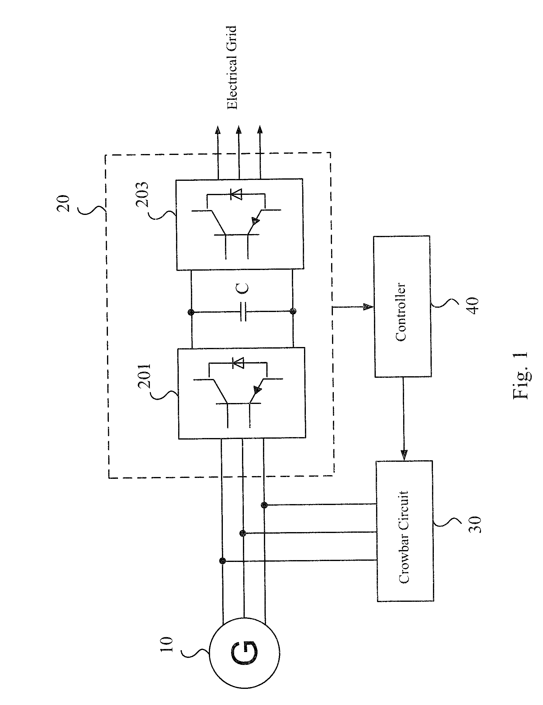
However, once the crowbar circuit fails, if the system does need to throw the crowbar circuit into the system but the crowbar circuit cannot operate normally, a fatal impact on the converter will be caused, which may even cause converter scrap in a serious case.

Method used


Image

  • Device and method for detecting crowbar circuit in wind turbine
  • Device and method for detecting crowbar circuit in wind turbine
  • Device and method for detecting crowbar circuit in wind turbine

Examples


Embodiment Construction

[0033]Specific embodiments of the present invention are further described in details below with reference to the accompanying drawings.

[0034]In order to make the technical contents of the present invention more detailed and more comprehensive, various embodiments of the present invention are described below with reference to the accompanying drawings. The same reference numbers are used in the drawings to refer to the same or like elements. However, the embodiments described herein do not intend to limit the present invention, and the description of structure operation does not intend to limit its implementation order. Any device with equivalent functions that is produced from a structure formed from recombination of elements shall fall within the scope of the present invention.

[0035]Moreover, the drawings are merely illustrative and are not drawn to the original size. On the other hand, well-known elements and steps are not described in the embodiments to avoid causing unnecessary ...


PUM


Abstract

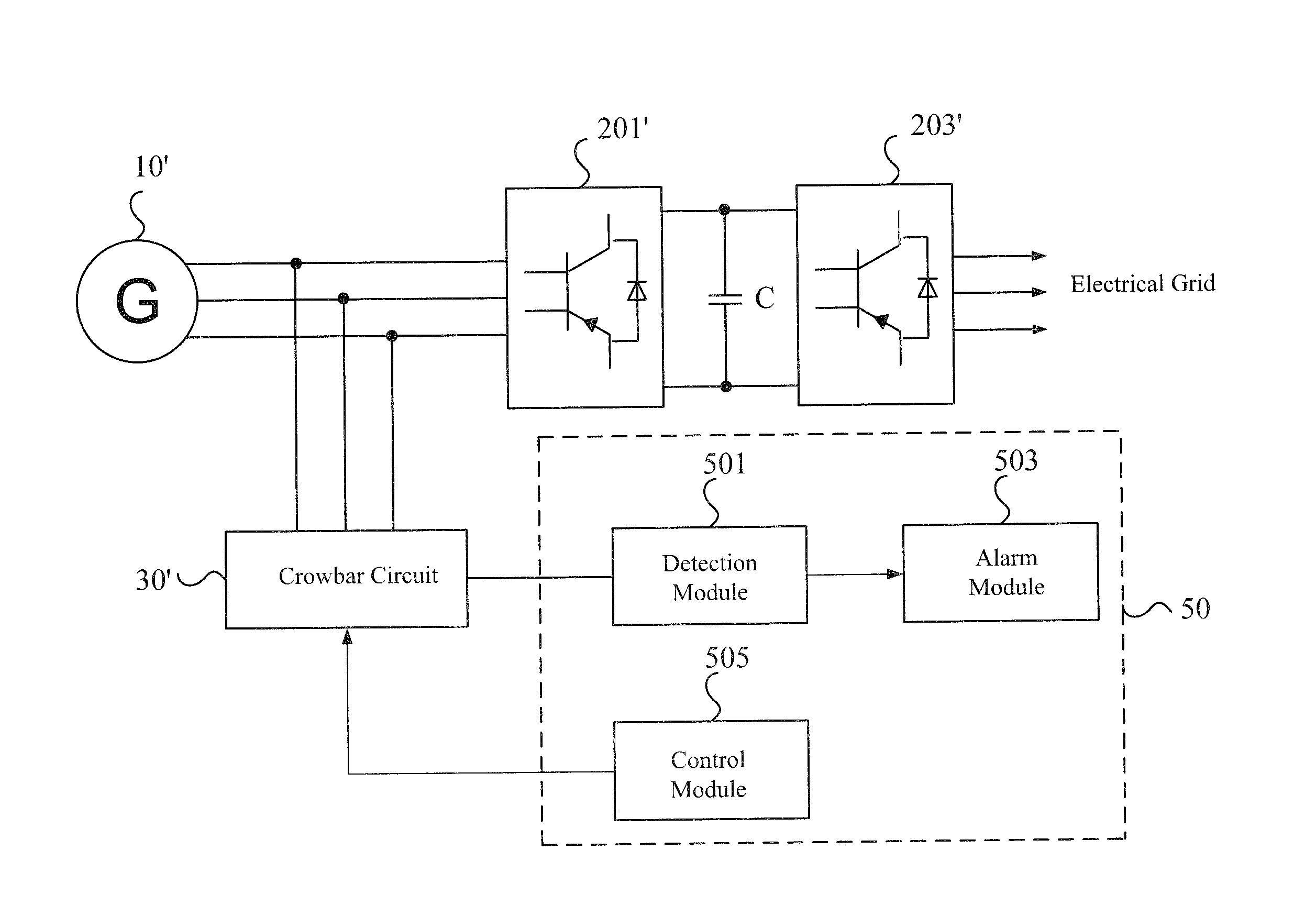
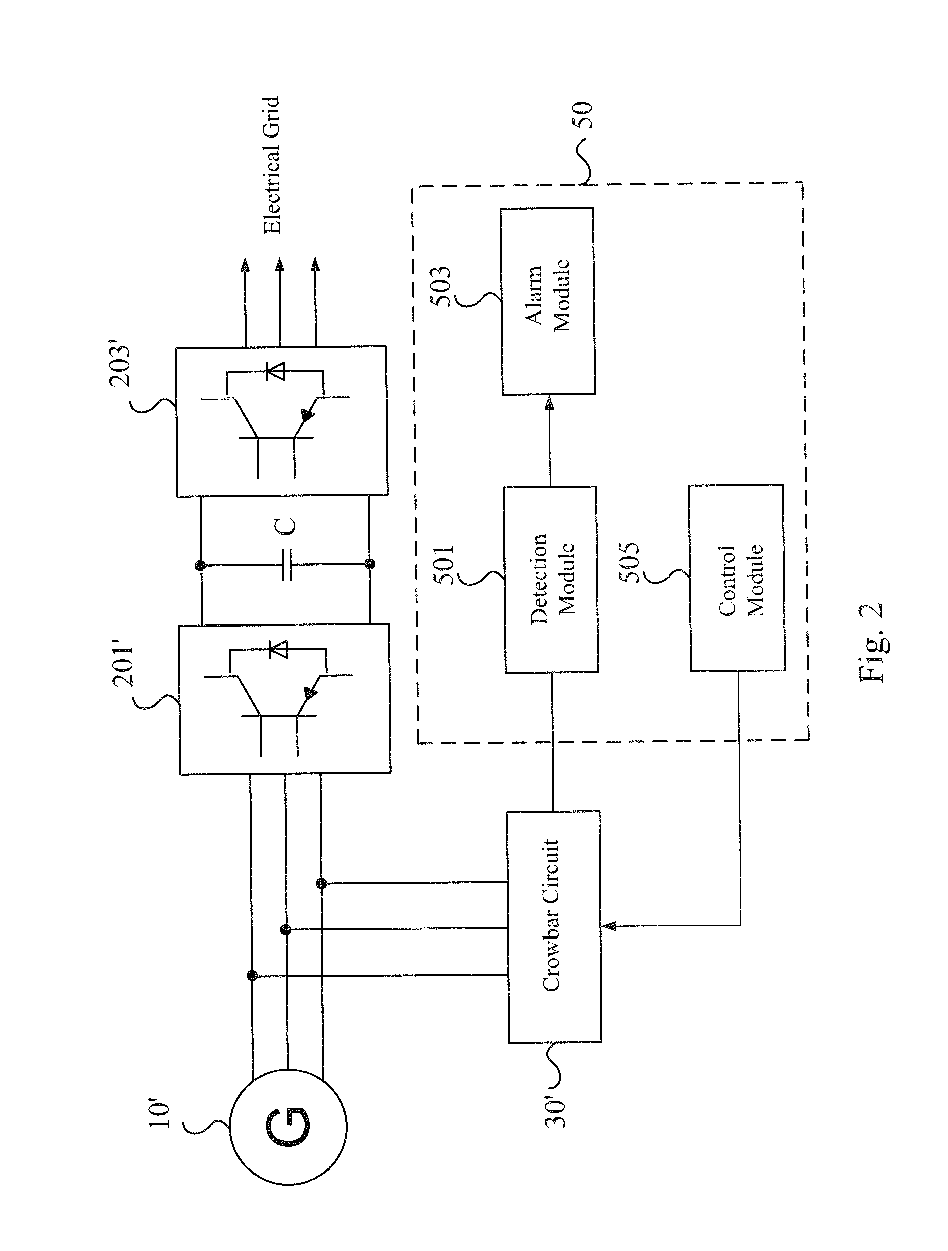
A device and a method for detecting a crowbar circuit in a wind turbine are provided, wherein the wind turbine comprises a converter electrically connected to the crowbar circuit, and the method comprises: electrically coupling a detection module to the crowbar circuit; inputting a first control signal into the crowbar circuit, to turn on the crowbar circuit; providing a three-phase voltage signal to the crowbar circuit via the converter, wherein voltage signals in any two adjacent phases has a predetermined phase angle difference; reading the first detection signal outputted by the detection module, to determine whether the crowbar circuit is normally thrown into the wind turbine; inputting a second control signal to the crowbar circuit, to turn off the crowbar circuit; and reading again the second detection signal outputted by the detection module, to determine whether the crowbar circuit is normally cut out from the wind turbine.

Description

RELATED APPLICATIONS[0001]This application claims priority to Chinese Application Serial Number 201110285663.9, filed Sep. 23, 2011, which is herein incorporated by reference by its entirety.BACKGROUND[0002]1. Field of Invention[0003]The present invention relates to the field of wind power generation. More particularly, the present invention relates to a device for detecting a crowbar circuit in the wind turbine and the method thereof.[0004]2. Description of Related Art[0005]With the increasing energy crisis and environmental issues, countries all over the world are vigorously developing renewable energy businesses, such as wind power generation and solar energy generation. Taking the wind power generation as an example, the installed wind power capacity in China grows rapidly, which is developed from a stall-regulated wind power system to a variable-speed and constant-frequency (VSCF) wind power system, and from a wind power system with a gear case to a direct-drive wind power syst...

Claims


Application Information

Patent Timeline
Patent Type & Authority Applications(United States)
IPC IPC(8): G01R29/00
CPCG01R31/24G05B19/054G01R31/42H01H47/002
Inventor CAO, LIANGCAI, LILU, YAN-SONG
Owner DELTA ELECTRONICS SHANGHAI CO LTD
Learn More