Piezoelectric Vibration Reed, Piezoelectric Vibrator, Oscillator, Electronic Instrument, and Radio Timepiece

a piezoelectric vibrator and piezoelectric technology, applied in piezoelectric/electrostrictive/magnetostrictive devices, piezoelectric/electrostrictive device details, instruments, etc., can solve the problems of easy stress concentration on these portions, inability to obtain sufficient strength of the vibrating arm portions, and deterioration of output signal quality, etc., to inhibit the lowering of rigidity and high reliability. , the effect of high performan

Active Publication Date: 2013-03-28
SII CRYSTAL TECH
View PDF9 Cites 17 Cited by
  • Summary
  • Abstract
  • Description
  • Claims
  • Application Information

AI Technical Summary

Benefits of technology

[0014]Accordingly, it is an object of the invention to provide a piezoelectric vibration reed which achieves downsizing while inhibiting lowering of the rigidity and prevention of deterioration of the quality of an output signal, a piezoelectric vibrator, an oscillator, an electronic instrument, and a radio timepiece having the same.

Problems solved by technology

Consequently, the equivalent series resistance value thereof (the CI (Crystal Impedance) value) is increased, and the quality of an output signal may be deteriorated.
In particular, when the groove portions are formed in the vicinity of connecting portions between the proximal end portions of the vibrating arm portions and the base portion, a sufficient strength of the vibrating arm portions cannot be obtained and, in addition, a stress concentration on these portions may easily occur.
Therefore, when an external impact or the like is applied on the piezoelectric vibration reed, the piezoelectric vibration reed is susceptible to breakage or the like starting from the portions in the vicinity of the connecting portions of the proximal end portions between the vibrating arm portions and the base portion.
In contrast, however, the larger the width of the groove portions, the more the rigidity of the vibrating arm portions in the direction of distortion or the direction of thickness thereof is decreased, so that the vibrating arm portions are susceptible to deformation.
Consequently, the vibrations might be excited in a vibration mode different from a desired vibration mode, which may results in deterioration of the quality of the output signal.

Method used


Image

  • Piezoelectric Vibration Reed, Piezoelectric Vibrator, Oscillator, Electronic Instrument, and Radio Timepiece
  • Piezoelectric Vibration Reed, Piezoelectric Vibrator, Oscillator, Electronic Instrument, and Radio Timepiece
  • Piezoelectric Vibration Reed, Piezoelectric Vibrator, Oscillator, Electronic Instrument, and Radio Timepiece

Examples


embodiment

Effect of Embodiment

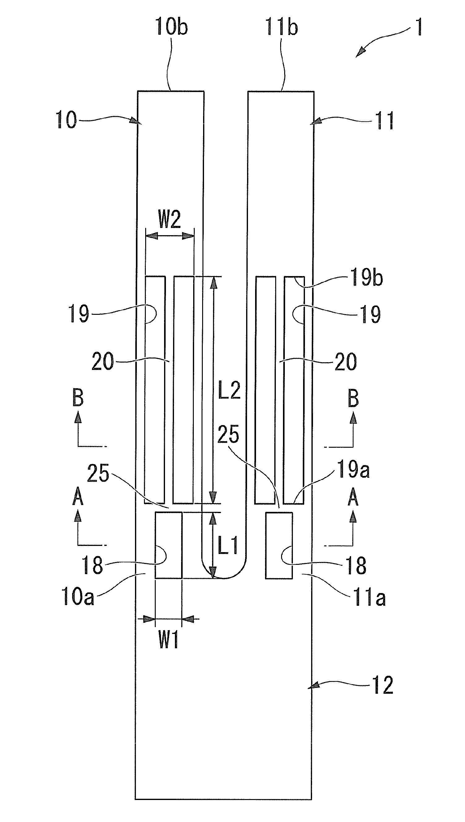
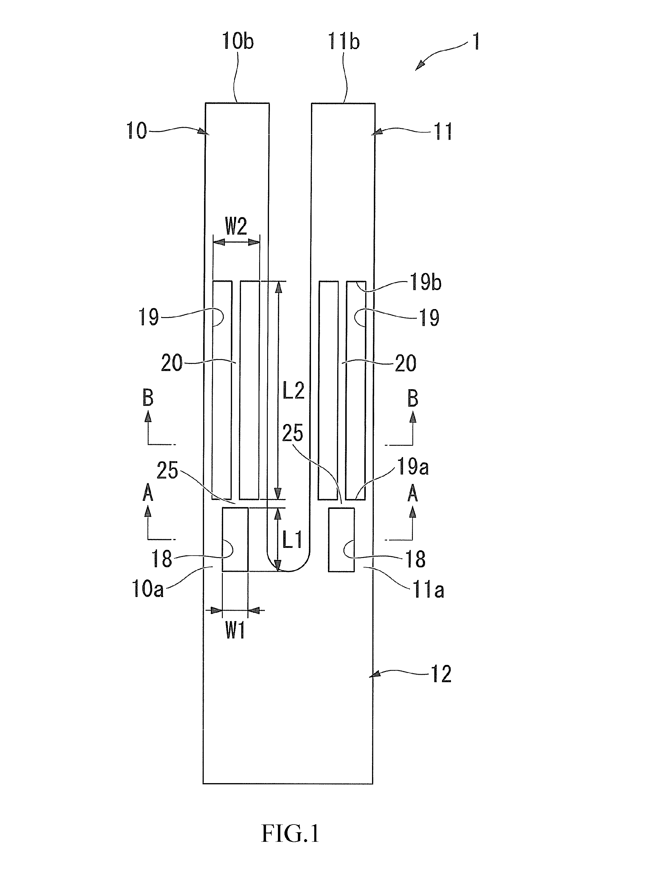
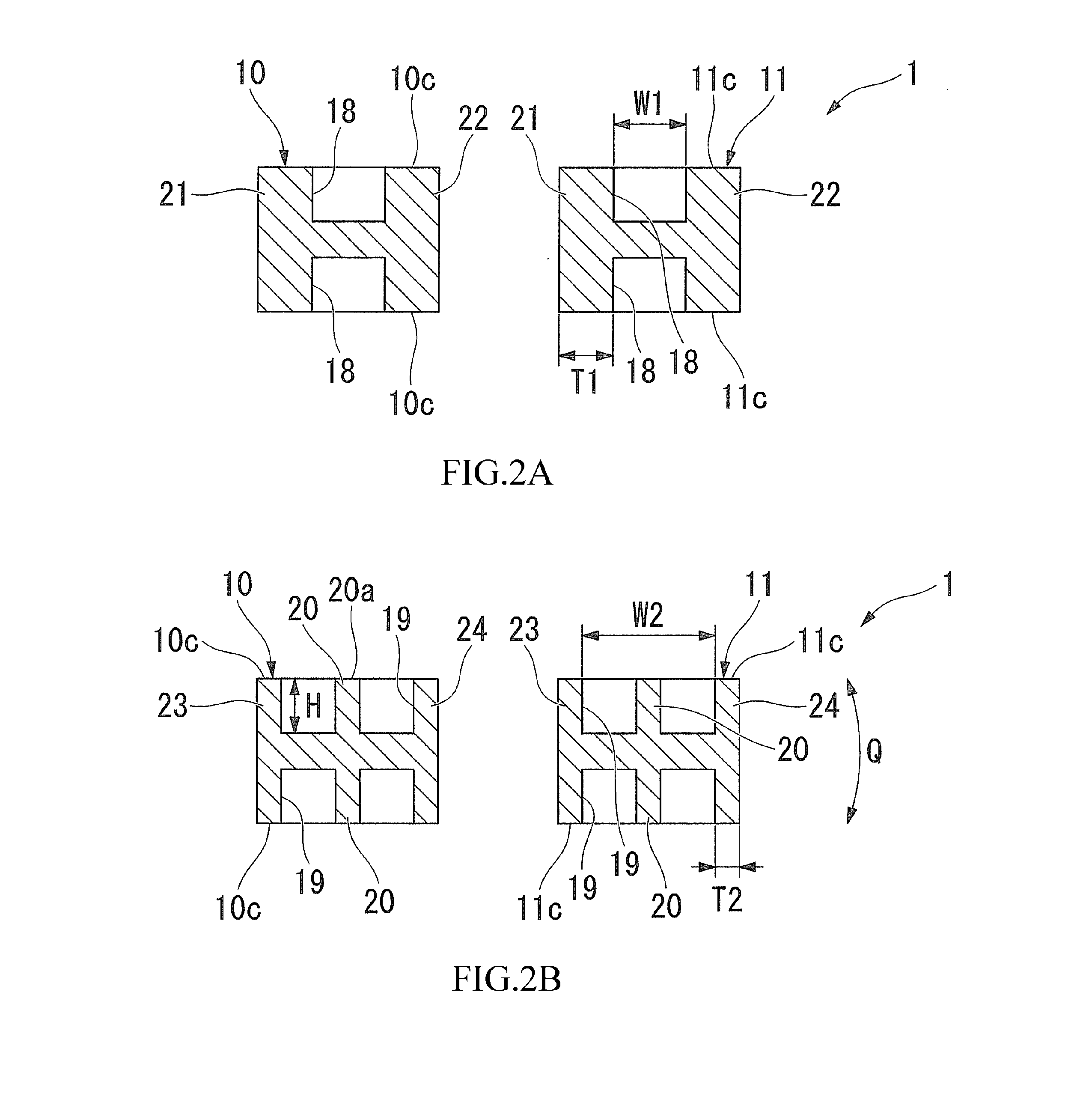
[0065]In the piezoelectric vibration reed 1 as described above, since the groove portions 18 formed on the proximal end portions 10a and 11a of the vibrating arm portions 10 and 11 are formed to be smaller in the width W1 and the length L1 than the groove portions 19 formed on the side of the distal end portions 10b and 11b with respect to the groove portions 18, the rigidity of the proximal end portions 10a and 11a of the vibrating arm portions 10 and 11 may be enhanced. Accordingly, the stress can be prevented from concentrating on the proximal end portions 10a and 11a of the vibrating arm portions 10 and 11, and the occurrence of breakage or the like of the piezoelectric vibration reed 1 is prevented even when an external impact or the like is applied to the piezoelectric vibration reed 1.

[0066]Since the groove portions 19 formed in the midpoints of the vibrating arm portions 10 and 11 in the longitudinal direction are provided with the reinforcing ribs 20, th...

first modification of embodiment

[0070]In the embodiment described above, the reinforcing ribs 20 are formed continuously in the longitudinal direction so as to connect the one ends 19a and the other ends 19b of the groove portions 19. However, the invention is not limited thereto.

[0071]For example, as shown in FIG. 3, reinforcing ribs 20A may be arranged intermittently along the longitudinal direction between the one ends 19a and the other ends 19b of the groove portions 19.

[0072]In this configuration as well, the same effects as the embodiment described above may be obtained.

[0073]Alternatively, the reinforcing ribs 20 may be extended in a cantilevered manner so as to extend along the longitudinal direction from the one ends 19a and the other ends 19b so as to oppose each other instead of connecting the one ends 19a and the other ends 19b of the groove portions 19 completely by being fixed at both ends. In other words, in this case, the reinforcing ribs 20 are discontinued in the midpoints of the groove portions ...

second modification of embodiment

[0077]Although the wall portions 25 positioned between the groove portions 18 and the groove portions 19 extend in the width directions of the vibrating arm portions 10 and 11 in the embodiment described above, the invention is not limited thereto.

[0078]For example, as shown in FIG. 4, wall portions (partitioning walls) 25A positioned between the groove portions 18 and the groove portions 19 may be extended in the direction intersecting the width directions of the vibrating arm portions 10 and 11 on the main surfaces 10c and 11c of the vibrating arm portions 10 and 11. The wall portions 25A in this modification are inclined toward the distal end portions 10b and 11b along the longitudinal direction of the vibrating arm portions 10 and 11 as it goes the centers from the both sides in the width direction.

[0079]In this configuration, since the wall portions 25A have not only a component in the width direction but also in the longitudinal direction, a reinforcing component with respect ...


PUM


Abstract

There is provided a piezoelectric vibration reed including a pair of vibrating arm portions arranged in parallel to each other and a base portion integrally fixing proximal end portions in the longitudinal direction of the pair of vibrating arm portions, wherein the pair of vibrating arm portions is formed with first groove portions positioned on the side of the proximal end portions of the vibrating arm portions and second groove portions positioned on the side of distal end portions of the vibrating arm portions with respect to the first groove portions on main surfaces, the width of the first groove portions along the width direction orthogonal to the longitudinal direction of the vibrating arm portions on the main surfaces of the vibrating arm portions is formed to be smaller than the second groove portions, and reinforcing ribs projecting from bottom surfaces of the second groove portions are formed in the second groove portions.

Description

RELATED APPLICATIONS[0001]This application claims priority under 35 U.S.C. §119 to Japanese Patent Application No. 2011-213019 filed on Sep. 28, 2011, the entire content of which is hereby incorporated by reference.BACKGROUND OF THE INVENTION[0002]1. Technical Field[0003]The present invention relates to a piezoelectric vibration reed, a piezoelectric vibrator, an oscillator, an electronic instrument, and a radio timepiece.[0004]2. Description of the Related Art[0005]In mobile phones or portable information terminal equipment, a piezoelectric vibrator using crystal or the like is employed as a timing source or a reference signal source of a time-of-day source or a control signal. Various types of the piezoelectric vibrators of this type are provided, and as one of these piezoelectric vibrators, a piezoelectric vibrator having so-called a tuning-fork-type piezoelectric vibration reed is known.[0006]The tuning-fork-type vibration reed includes a pair of vibrating arm portions disposed ...

Claims


Application Information

Patent Timeline
Patent Type & Authority Applications(United States)
IPC IPC(8): H01L41/04
CPCG04R20/10H03H9/1021H03H9/0595H03H9/21
Inventor ARIMATSU, DAISHI
Owner SII CRYSTAL TECH
Why Eureka
Try Eureka