Combustor and method for supplying fuel to a combustor

a combustor and combustor technology, applied in the direction of combustion process, hot gas positive displacement engine plant, lighting and heating apparatus, etc., can solve the problems of increasing the disassociation rate of diatomic nitrogen, and affecting the chemical reaction rate of combustion gases

Active Publication Date: 2013-03-28
GENERAL ELECTRIC CO
View PDF10 Cites 38 Cited by
  • Summary
  • Abstract
  • Description
  • Claims
  • Application Information

AI Technical Summary

Benefits of technology

The invention described in this patent text has advantages that can be easily understood. It is designed to improve the performance of electrical circuits. The technical effects of this invention include improved stability, reliability, and reduced latency. These benefits can be achieved by incorporating certain features into the circuit design, such as redundant components, signal timing optimizations, and sensory feedback. By implementing these features, the circuit can better control its performance and adapt to different conditions, making it more reliable and efficient. Overall, this invention can enhance the performance of electrical circuits and improve their overall quality.

Problems solved by technology

However, higher combustion gas temperatures also promote flashback or flame holding conditions in which the combustion flame migrates towards the fuel being supplied by the nozzles, possibly causing severe damage to the nozzles in a relatively short amount of time.
In addition, localized hot streaks in the combustion chamber may increase the disassociation rate of diatomic nitrogen, increasing the production of nitrogen oxides (NOx) at higher combustion gas temperatures.
Conversely, lower combustion gas temperatures associated with reduced fuel flow and / or part load operation (turndown) generally reduce the chemical reaction rates of the combustion gases, increasing the production of carbon monoxide and unburned hydrocarbons.

Method used


Image

  • Combustor and method for supplying fuel to a combustor
  • Combustor and method for supplying fuel to a combustor
  • Combustor and method for supplying fuel to a combustor

Examples


first embodiment

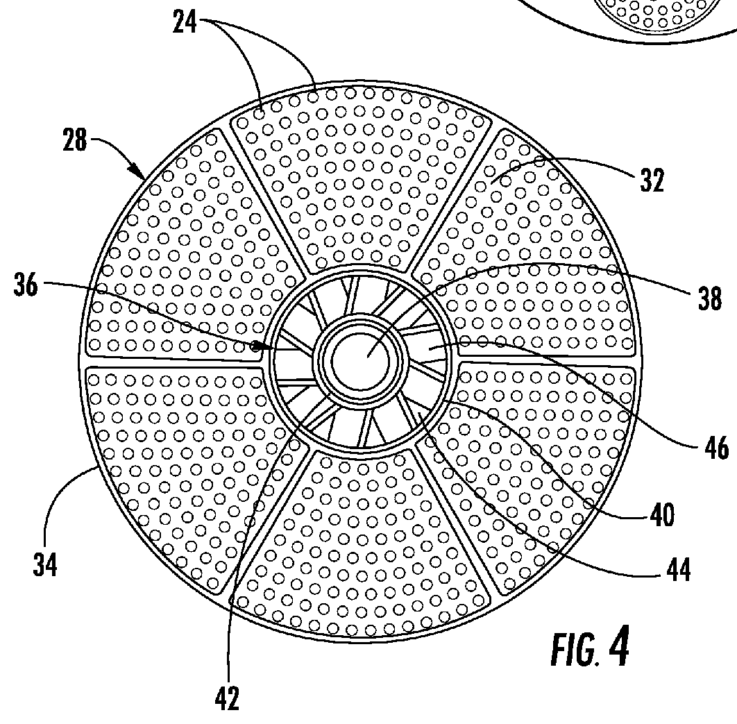
[0026]FIG. 6 provides an enlarged cross-section view of a portion of the end cap 28 shown in FIG. 5 according to the present invention. As shown, the first barrier 48 extends radially in the end cap 28 between the upstream and downstream surfaces 30, 32, and the tubes 24 extend from the upstream surface 30 through the first barrier 48 and the downstream surface 32 to provide fluid communication through the end cap 28. As further shown, the first conduit 54 is in fluid communication with the first plenum 50, and the second conduit 56 is in fluid communication with the second plenum 52.

[0027]The tubes 24 may be arranged into multiple circuits that enable varying flow rates of the fuel and / or the diluent to each circuit. For example, as shown in FIG. 6, a first circuit 58 of tubes 24 may include one or more fluid passages 60 that provide fluid communication from the first plenum 50 through each tube 24 in the first circuit 58, and a second circuit 62 of tubes 24 may include one or more...

second embodiment

[0030]FIG. 7 provides an enlarged cross-section view of a portion of the end cap 28 shown in FIG. 5 according to the present invention. In this particular embodiment, a second barrier 70 extends radially in the end cap 28 between the first barrier 48 and the downstream surface 32 to at least partially define a third plenum 72 in the end cap 28 downstream from the second barrier 70. Specifically, the second barrier 70, downstream surface 32, and cap shield 34 define the third plenum 72. In addition, one or more ports 74 through the cap shield 34 provide fluid communication through the cap shield 34 to the third plenum 72. In this manner, at least a portion of the working fluid may flow into the third plenum 72 to flow around the first and / or second circuits 58, 62 of tubes 24 to provide convective cooling to the tubes 24. The working fluid may then flow through gaps 76 between the downstream surface 32 and the tubes 24 before flowing into the combustion chamber 26.

third embodiment

[0031]FIG. 8 provides an enlarged cross-section view of a portion of the end cap 28 shown in FIG. 5 according to the present invention. In this particular embodiment, the first and second conduits 54, 56 are curved to more readily absorb thermal expansion and contraction in the combustor 10. In addition, the second circuit 62 of tubes 24 includes fluid passages 60 that provide fluid communication from both the first and second plenums 50, 52 through one or more tubes 24 in the second circuit 62. As a result, fuel and / or diluent supplied to the first circuit 58 of tubes 24 may also be supplied to one or more tubes 24 in the second circuit 62.

[0032]The axial position, number, and size of the fluid passages 60 in each circuit 58, 62 may be selected to optimize the fuel flow through each tube 24 at various operating levels while also enhancing the combustion dynamics. Specifically, the fluid passages 60 upstream from the first baffle 64 allow more time for convective mixing between the ...


PUM


Abstract

A combustor includes an end cap having an upstream surface axially separated from a downstream surface and a cap shield circumferentially surrounding the upstream and downstream surfaces. A first circuit of tubes extends from the upstream surface through the downstream surface. A first fuel plenum is in fluid communication with the first circuit of tubes. A second circuit of tubes extends from the upstream surface through the downstream surface. A second fuel plenum downstream from the first fuel plenum is in fluid communication with the second circuit of tubes. A method for supplying fuel to a combustor includes flowing a working fluid through tubes, flowing fuel or diluent from a first fuel plenum through a first circuit of tubes, and flowing fuel or diluent from a second fuel plenum through a second circuit of tubes, wherein the second fuel plenum is downstream from the first fuel plenum.

Description

FIELD OF THE INVENTION[0001]The present invention generally involves a combustor and method for supplying fuel to a combustor.BACKGROUND OF THE INVENTION[0002]Combustors are commonly used in industrial and power generation operations to ignite fuel to produce combustion gases having a high temperature and pressure. For example, gas turbines typically include one or more combustors to generate power or thrust. A typical gas turbine used to generate electrical power includes an axial compressor at the front, one or more combustors around the middle, and a turbine at the rear. Ambient air may be supplied to the compressor, and rotating blades and stationary vanes in the compressor progressively impart kinetic energy to the working fluid (air) to produce a compressed working fluid at a highly energized state. The compressed working fluid exits the compressor and flows through one or more nozzles into a combustion chamber in each combustor where the compressed working fluid mixes with fu...

Claims


Application Information

Patent Timeline
Patent Type & Authority Applications(United States)
IPC IPC(8): F23R3/28
CPCF23R3/36F23R3/286
Inventor BERRY, JONATHAN DWIGHT
Owner GENERAL ELECTRIC CO
Why Eureka
Try Eureka