
Catalyst containing oxygen transport membrane

a technology of oxygen transport membrane and catalyst, which is applied in the direction of catalysts, physical/chemical processes, membranes, etc., can solve the problems of material fragility, material weakening, and dense layer,

Inactive Publication Date: 2013-03-21
LANE JONATHAN A +2
View PDF0 Cites 26 Cited by
  • Summary
  • Abstract
  • Description
  • Claims
  • Application Information

AI Technical Summary

Benefits of technology

The patent describes a process to help a solution infiltrate a porous support layer and prevent air bubbles from getting in. This is important because air bubbles can prevent the solution from fully soaking the support layer, which can affect its effectiveness. The process involves using a vacuum to remove air and create a pressure on the other side of the support layer, which assists in the solution's wicking process. This ensures that the solution can flow all the way through the support layer and into an intermediate layer without being hindered by air bubbles.

Problems solved by technology

Another limiting factor to the performance of an oxygen transport membrane concerns the supporting layers that, although can be active, that is oxygen ion or electron conducting, the layers themselves can consist of a network of interconnected pores that can limit diffusion of the oxygen or fuel or other substance through the membrane to react with the oxygen.
The high porosity, however, tends to weaken such a structure.
The resulting heat will heat the oxygen transport membrane up to operational temperature and excess heat can be used for other purposes, for example, heating a fluid, for example, raising steam in a boiler or in the combustible substance itself While perovskite structured materials will exhibit a high oxygen flux, such materials tend to be very fragile under operational conditions such as in the heating of a fluid.
The end result is that at the fuel side, the material will tend to expand relative to the air side and a dense layer will therefore, tend to fracture.
However, the problem with the use of a fluorite structure material, such as a stabilized zirconia, is that such a material has lower oxygen ion conductivity.

Method used


Image

  • Catalyst containing oxygen transport membrane
  • Catalyst containing oxygen transport membrane
  • Catalyst containing oxygen transport membrane

Examples


Embodiment Construction

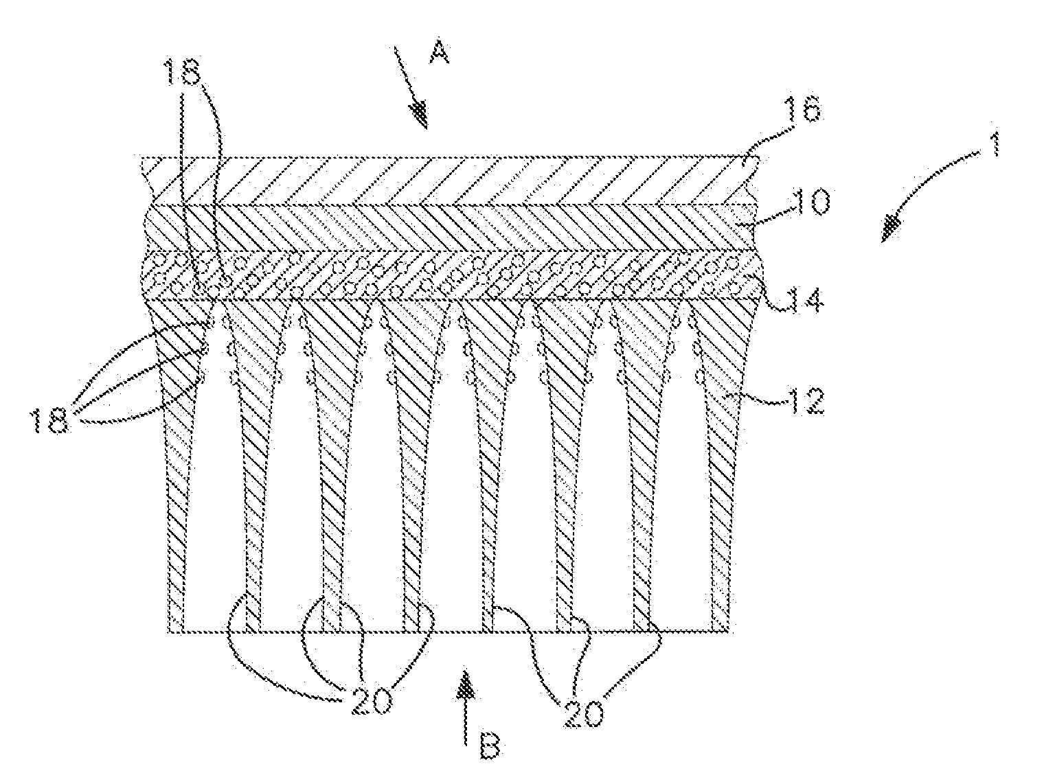
[0030]With reference to FIG. 1, a sectional view of a composite oxygen transport membrane element 1 in accordance with the present invention is illustrated. As could be appreciated by those skilled in the art, such composite oxygen transport membrane element 1 could be in the form of a tube or a flat plate. Such composite oxygen transport membrane element 1 would be one of a series of such elements situated within a device to heat a fluid such as in a boiler or other reactor having such a heating requirement.

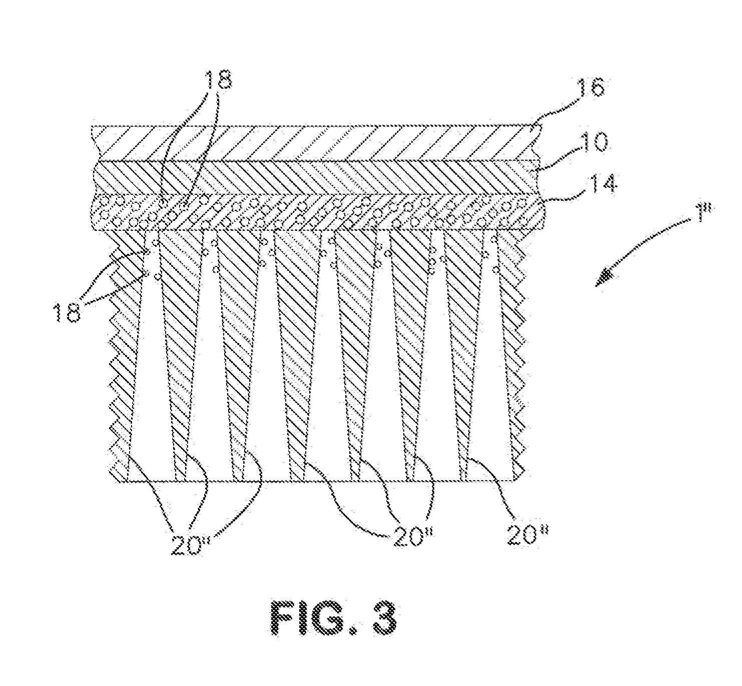
[0031]Composite oxygen transport membrane element 1 is provided with a dense layer 10, a porous support layer 12 and an intermediate porous layer 14 located between the dense layer 10 and the porous support layer 12. A preferable option is, as illustrated, to also include a porous surface exchange layer 16 in contact with the dense layer 10, opposite to the intermediate porous layer 14. Catalyst particles 18 are located in the intermediate porous layer 14 that are formed of a ca...


PUM

PropertyMeasurementUnit
Lengthaaaaaaaaaa
Lengthaaaaaaaaaa
Lengthaaaaaaaaaa

Abstract

A composite oxygen transport membrane having a dense layer, a porous support layer and an intermediate porous layer located between the dense layer and the porous support layer. Both the dense layer and the intermediate porous layer are formed from an ionic conductive material to conduct oxygen ions and an electrically conductive material to conduct electrons. The porous support layer has a high permeability, high porosity, and a microstructure exhibiting substantially uniform pore size distribution as a result of using PMMA pore forming materials or a bi-modal particle size distribution of the porous support layer materials. Catalyst particles selected to promote oxidation of a combustible substance are located in the intermediate porous layer and in the porous support adjacent to the intermediate porous layer. The catalyst particles can be formed by wicking a solution of catalyst precursors through the porous support toward the intermediate porous layer.

Description

CROSS REFERENCE TO RELATED APPLICATIONS [0001]The present application is a continuation-in part application of U.S. patent application Ser. No. 12 / 968,699; filed Dec. 15, 2010, which is incorporated by reference herein in its entirety.U.S. GOVERNMENT RIGHTS [0002]The invention disclosed and claimed herein was made with United States Government support under Cooperative Agreement number DE-FC26-07NT43088 awarded by the U.S. Department of Energy. The United States Government has certain rights in this invention.FIELD OF THE INVENTION [0003]The present invention relates to a composite oxygen transport membrane in which catalyst particles, selected to promote oxidation of a combustible substance, are located within an intermediate porous layer that is in turn located between a dense layer and a porous support layer and within the porous support and a method of applying the catalyst to the intermediate porous layer and the porous support layer through wicking of catalyst precursors throu...

Claims


Application Information

Patent Timeline
IPC IPC(8): B01J31/06B01J27/138
CPCB01J31/06B01J27/138B01J2523/00B01J37/0201B01J35/065B01J35/023B01J35/0033B01J35/002B01J23/10B01J23/002C01B2210/0046B01D2325/10B01D2325/021C01B13/0255B01D71/024B01D69/12B01D53/228B01J2523/24B01J2523/3706B01J2523/55B01J2523/67B01J2523/842B01J2523/3712B01J2523/72B01J35/30B01J35/33B01J35/40B01J35/59B01D69/1216B01D2325/0214B01D71/0271
Inventor LANE, JONATHAN A.WILSON, JAMIE R.CHRISTIE, GERVASE MAXWELL
Owner LANE JONATHAN A
Learn More