Eureka AIR delivers breakthrough ideas for toughest innovation challenges, trusted by R&D personnel around the world.

Oxy-Fuel Burner Arrangement

a burner arrangement and burner technology, applied in the field of burners, can solve the problems of glass contamination or volatilization of the high boiling components of glass, difficult identification of nozzle clogging problems, and glass quality problems,

Inactive Publication Date: 2013-03-21
AIR PROD & CHEM INC
View PDF9 Cites 15 Cited by
  • Summary
  • Abstract
  • Description
  • Claims
  • Application Information

AI Technical Summary

Benefits of technology

This patent describes an oxy-fuel burner that has a fuel conduit surrounded by an oxygen conduit. This burner is placed in a precombustor to increase the mixing of the fuel and oxygen gases, resulting in a shorter flame without causing overheating of the burner components. The invention also includes a method for using this burner in transport channels for molten materials. The shape of the nozzle aperture and the cross-sectional geometry of the first conduit enhance the entrainment of the second gas, producing a flat flame. The asymmetric shape of the precombustor outlet further helps in stabilizing the gas flows. This patent provides technical means to achieve a more efficient and stable oxy-fuel flame for industrial applications.

Problems solved by technology

Small nozzle tip openings are easily clogged from these deposits, causing glass contamination with molten metal from the damaged burner and unfavorable glass temperature distributions in the conditioning area that lead to glass quality issues.
This nozzle clogging problem is not easy to identify before glass quality issues arise, since there is often a lack of a clear view of the flames in the glass conditioning and forehearth areas.
Furthermore, partial clogging of the nozzle can misdirect the oxy-fuel flame and lead to burner block damage or direct flame impingement on the glass surface, causing glass contamination or volatilization of the high boiling components of the glass.
When employing a flame in a distribution canal which extends beyond the zone near the walls of the canal and which therefore also heats the molten material in the central zone of the canal, there is substantial risk of reboiling the molten material in this zone and, therefore, of having an end product that exhibits inhomogeneities and corresponding defects.
The width of the molten material distribution channels may be small creating a challenge in maintaining a homogeneous temperature distribution while firing the burners at a firing rate sufficient to maintain the optimal glass temperature.
For example, fiberglass forehearths are very narrow, often less than 18 inches wide which can present a challenge of supplying sufficient thermal energy to the system without flame impingement on the opposite wall.
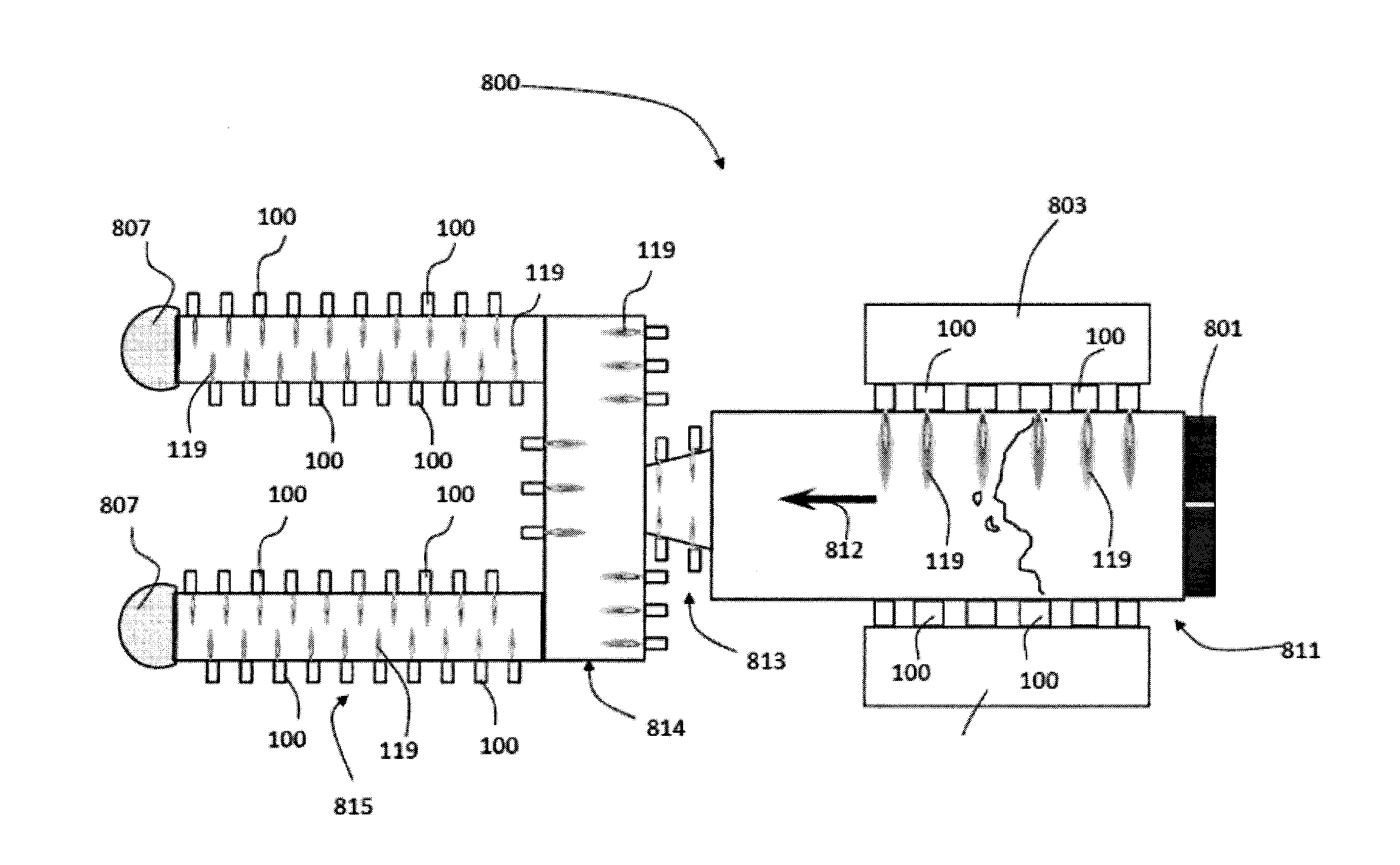
This opposed air-fuel burner configuration creates a lot of turbulence in the combustion chamber which can create hot spots.
Hot spots in the combustion chamber can also be generated if the flows to the opposed air-fuel burners are not well balanced or the burners are poorly aligned when installed.
Even when this opposed installation method is employed, air-fuel burners are often unable to provide the desired amount of energy to the chamber, limiting glass temperature, compromising product quality and reducing production rates.
Gollahalli's tests were limited to the open air firing of air fuel flames from burners without precombustors.
One drawback of the delayed mixing approach is that the flames are too long to supply the needed energy to channels, canals and forehearths without overheating the glass in the center of a wide forehearth or overheating the refractory on the opposite wall of a narrow forehearth, canal or small specialty glass melting furnace.
Another drawback is that the '058 flames do not are not capable of maintaining sufficient temperature homogeneity of the glass inside these glass conditioning structures, adversely affecting product quality.
Kobayashi utilizes a complicated design and does not utilize fluid dynamics from the nozzle shape and burner operation to alter the flame geometry.
However, the design disclosed has limited ability to alter the flame geometry and provide uniformity in heating.

Method used


Image

  • Oxy-Fuel Burner Arrangement
  • Oxy-Fuel Burner Arrangement
  • Oxy-Fuel Burner Arrangement

Examples


example 1

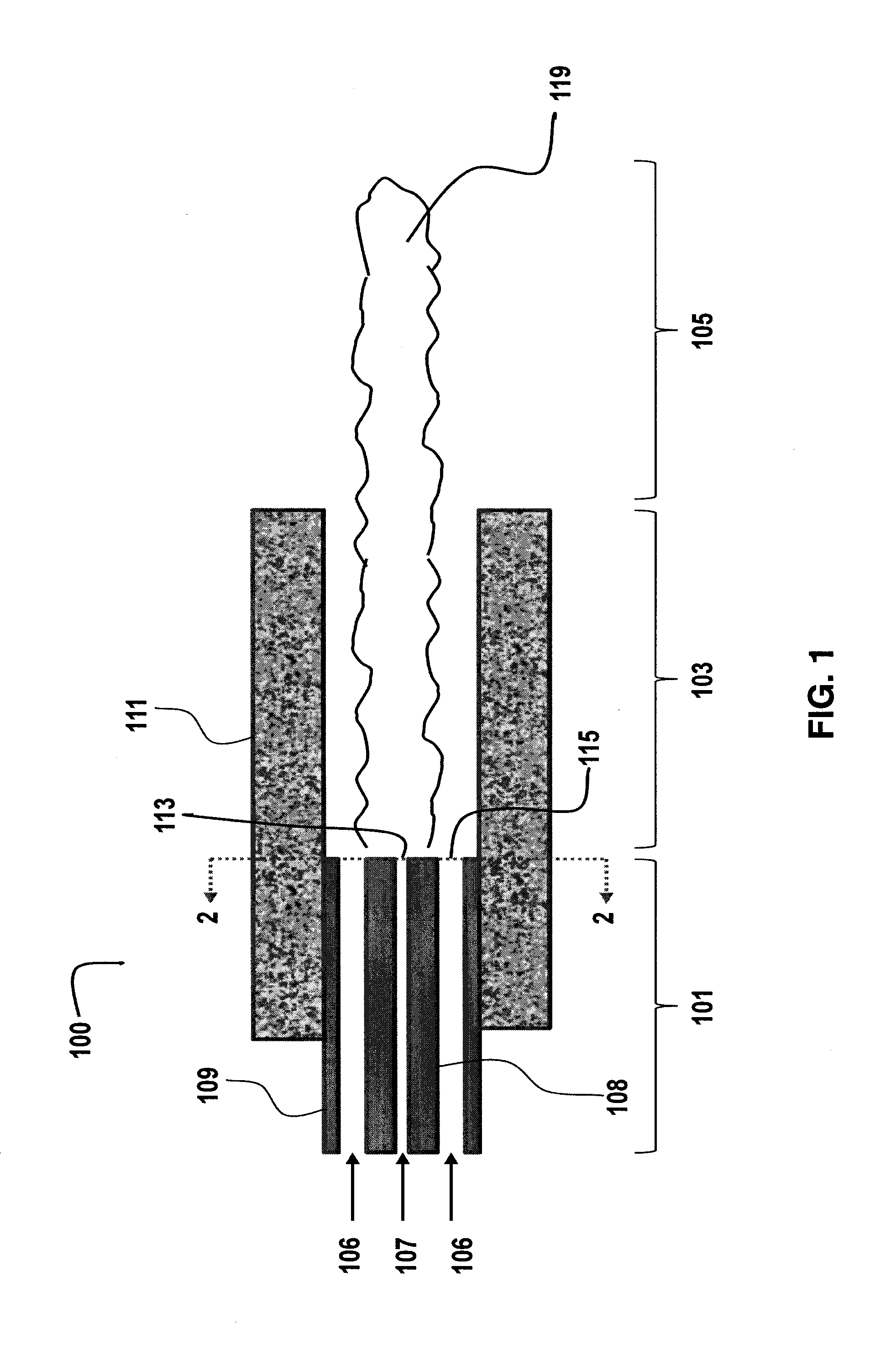
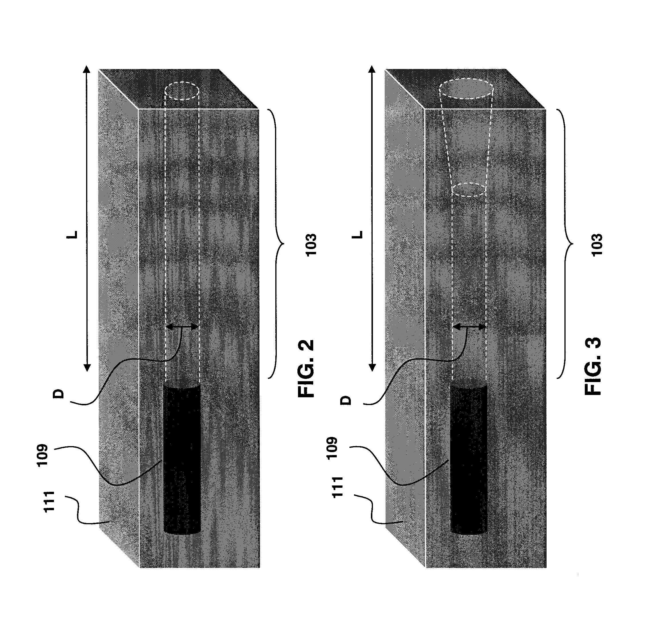
[0063]This Example evaluates the effect of fuel nozzle aperture geometry on the flame produced from the burner assembly in FIG. 1 with a cylindrical precombustor using fuel nozzle apertures shown in FIGS. 6-11. The burner was fired while equipped with each of the fuel nozzle apertures in a single burner test mode at a firing rate of 20,000 Btu / h in a refractory lined box. The burner tests of this example used a cylindrical precombustor length / diameter (L / D) of 6. The results of the evaluation are shown below in Table 1.

TABLE 1Visible Flame LengthFuel velocity / Fuel NozzleCompared with CircleOxygenApertureAspect RatioNozzlevelocityCircle1.0—3.9Square1.0Unchanged8.1Cross1.0Unchanged8.1Clover1.07Unchanged8.1Snowman1.8Unchanged8.1Slot3.0Shortened8.1Two Half Circles4.17Shortened6.4

[0064]The results of these single burner firing tests show that changing the fuel nozzle aperture geometry has no effect on the flames produced by this burner if the aperture has an aspect ratio of 1.8 or less. ...

example 2

[0065]Example 2 is an evaluation of flame characteristics for a burner firing with a Circle (symmetric) and a burner firing with a Slot (non-circular) fuel nozzles aperture (shown in FIGS. 6-7), in single and multiple burner configurations in a refractory lined box. The cylindrical precombustor L / D for these tests was 6. Visible flame lengths are given in Table 2 (below). The visible flame lengths for both fuel nozzle aperture geometries shortened when the burners were fired in a multiple burner configuration as compared with a single burner configuration. The non-circular nozzle aperture geometry produced a shorter flame than the symmetric nozzle aperture geometry in both the single and the multiple burner firing configurations. Two different firing rates were tested in the multiple burner configuration. The non-circular nozzle aperture geometry produced a shorter flame than the symmetric nozzle aperture geometry at both firing rates. The precombustor geometry influences the length...

example 3

[0066]Example 3 is an evaluation of the temperature of the precombustor wall at various distances from the precombustor outlet for burners firing symmetric and non-circular fuel nozzle apertures of FIGS. 6 and 7 (TC1 is closest to the precombustor outlet, TC2 is further from the precombustor outlet than TC1 and TC3 is the furthest from the precombustor outlet). The temperatures were recorded after firing four burners into a refractory lined box at 15,000 Btu / h per burner for 4.75 hr, to achieve thermal equilibrium. The floor temperature range is the difference between the maximum and minimum temperature recorded from four thermocouples placed at regular intervals throughout and a height of one inch above the floor of the refractory lined box. The floor temperatures represent the molten material temperature. The results of the evaluation are shown in Table 3 below.

TABLE 3Circle Fuel NozzleSlot Fuel NozzleΔ T(equilibrated 4.75 hours)(equilibrated 4.75 hours)CircleTemperatureTemperatur...


PUM

PropertyMeasurementUnit
aspect ratioaaaaaaaaaa

Abstract

An oxy-fuel burner arrangement having a first conduit having a nozzle aperture with an aspect ratio, D1 / D2, of greater than or equal to about 2.0. The first conduit is arranged and disposed to provide a first fluid stream, where the first fluid stream is a combustible fuel. The burner arrangement further includes at least one second conduit arranged and disposed to provide a second gas stream circumferentially around the first fluid stream, where the second gas stream includes oxygen. A precombustor is arranged and disposed to receive the first fluid stream and second gas stream where an oxy-fuel flame is produced. The geometry of the nozzle aperture and the cross-sectional geometry of the first conduit are dissimilar.

Description

[0001]This Application claims the benefit of U.S. Provisional Application No. 61 / 451,250, filed on Mar. 10, 2011. The disclosure of the Provisional Application is hereby incorporated by reference in its entirety.BACKGROUND OF THE INVENTION[0002]The instant invention relates to burners and methods for using the burners for industrial heating including oxy-fuel burners employed in the transport channels leaving a glass melting furnace and those employed in small specialty glass melters.[0003]Air-fuel glass conditioning burners, such as the burners used in refining or in the forehearth, do not use preheated air. Much of the energy supplied to the conditioning operation from the air-fuel burners is used to heat the nitrogen in the air. Efficiency improvement achievable by switching from air-fuel to oxy-fuel burners is at least 60%. Typical oxy-fuel glass conditioning burners are designed with high fuel velocities for rapid mixing of fuel and oxygen at the oxygen and fuel gas outlets. Th...

Claims


Application Information

Patent Timeline
Patent Type & Authority Applications(United States)
IPC IPC(8): F23D14/58F23C5/14C03B7/06F23D14/32
CPCF23C5/28F23D14/22F23D14/58F23D14/32F23M5/025C03B7/065F23C5/14F23D14/84F23C3/00Y02E20/34F23L7/00
Inventor COLE, JEFFREY D.JOHNSON, LEIGHTA MAUREENMONROIG, LOUIS WALTERSLAVEJKOV, ALEKSANDAR GEORGI
Owner AIR PROD & CHEM INC
Why Eureka
Eureka Blog
Learn More