
Method and device for determining a current angular position of a rotatable magnetic component in an electric drive

a technology of rotatable magnetic components and electric drives, which is applied in the direction of electronic commutation motor control, galvano-magnetic devices, instruments, etc., can solve the problems of complex calculation methods, inability to measure rotor angles, and inability to differentiate between rotor angles of x° and one of x°

Active Publication Date: 2013-03-21
ROBERT BOSCH GMBH
View PDF3 Cites 5 Cited by
  • Summary
  • Abstract
  • Description
  • Claims
  • Application Information

AI Technical Summary

Benefits of technology

The present invention provides an angle sensor system that can accurately measure angle values in a limited range, without additional components or complex calculations. This system is advantageously used in electric drives with an uneven number of pole pairs, such as electric tools, electric steering systems, and hybrid drives. By eliminating additional components, the angle sensor system has lower computational complexity and lower installation and costs compared to conventional magnetic field sensor arrangements. The use of this angle sensor system is thus advantageous in various applications such as electric vehicles and tools.

Problems solved by technology

However, as a result it is not possible to measure a rotor angle which is unambiguous in an unlimited angle range from 0 to 360° but rather only a rotor angle which is unambiguous in a limited angle range from 0 to 180°.
It is therefore not possible to differentiate between a rotor angle of x° and one of x°+180°.
However, these angle-estimating methods require complex calculations, generate noise and are less accurate than if an angle sensor system is used.

Method used


Image

  • Method and device for determining a current angular position of a rotatable magnetic component in an electric drive
  • Method and device for determining a current angular position of a rotatable magnetic component in an electric drive
  • Method and device for determining a current angular position of a rotatable magnetic component in an electric drive

Examples


Embodiment Construction

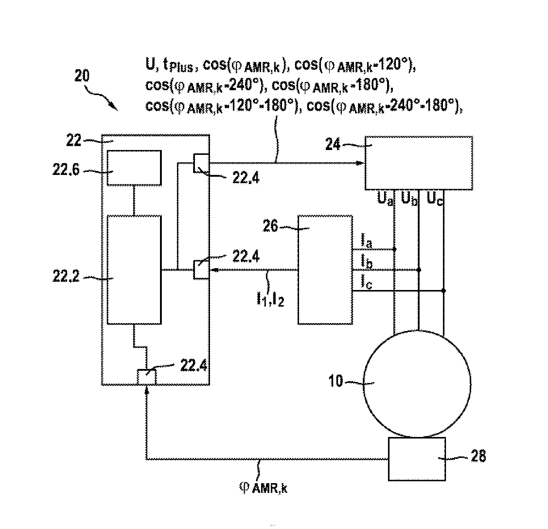
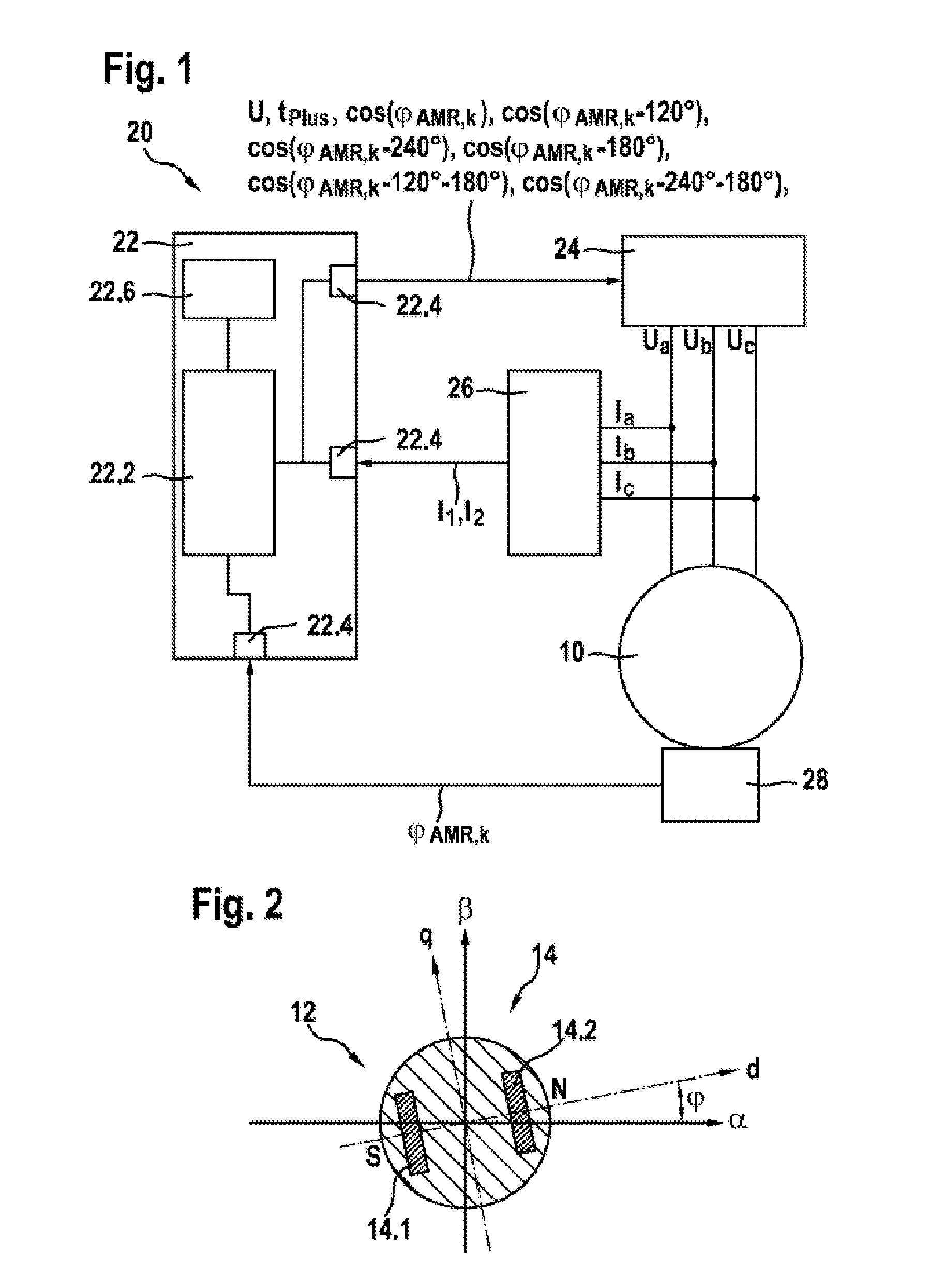
[0031]As is apparent from FIGS. 1 and 2, the illustrated exemplary embodiment of a device 20 according to the invention for determining a current angular position of a rotatable magnetic component 12 in an electric drive 10, which has a synchronous machine 10 with a rotor 12 in the illustrated exemplary embodiment, comprises an angle sensor system 28 which unambiguously measures a current angle measured value (ΦAMR,k of the rotor 12 within a predefined limited angle range which is 0 to 180° in the illustrated exemplary embodiment. In addition, the illustrated electric drive or the synchronous machine 10 has an uneven number Zp of pole pairs.

[0032]According to the invention, an evaluation and / or control unit 22 receives, via an interface unit 22.4, information about the current angle measured value ΦAMR,k, which is measured unambiguously in the limited angle range, and converts this measured current angle measured value ΦAMR,k into an unambiguous current angular position Φk in an unl...


PUM


Abstract

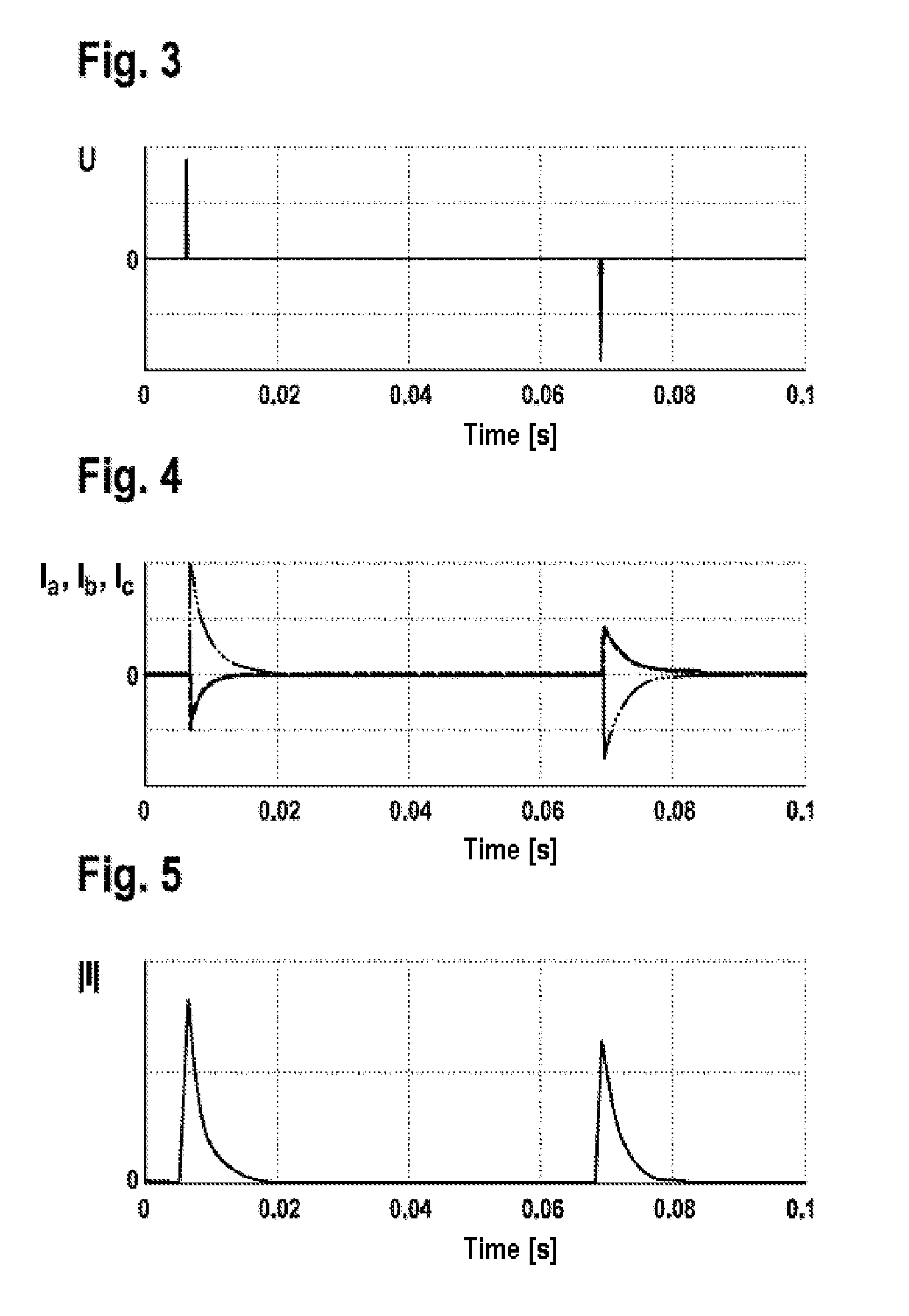
The invention relates to a method for determining the actual angle position of a rotatable magnetic component in an electric drive (10) having an odd number of pole pairs. An actual angle measurement value (ΦAMR,k) of the rotatable component is measured using an angle sensor (28) which only measures the actual angle measurement value (ΦAMR,k) within a predefined reduced angular area, and an associated device (20) for determining an actual angle position of a rotatable magnetic component in an electric drive (10). According to the invention, the actual angle measurement value (ΦAMR,k) measured exclusively for the reduced angular area is converted using the direction and the sign of the magnetic field of the rotatable magnetic component in a clear angular position in non-reduced angular area, the direction and sign of the magnetic field of the rotatable magnetic element (12) being determined by applying first test impulses (Ua, Ub, Uc) to the electric drive (10) and by evaluating the resulting second test impulses (I1, I2, Ia, Ib, Ic) which are produced in the electric drive (10) in reaction with the applied first test impulses (Ua, Ub, Uc).

Description

BACKGROUND OF THE INVENTION[0001]The invention is based on a method for determining a current angular position of a rotatable magnetic component in an electric drive, and on a device for determining a current angular position of a rotatable magnetic component in an electric drive.[0002]Drives which have a variable rotational speed and are based on synchronous machines constitute the prior art. In order to be able to correctly actuate the synchronous machine, information about the current rotor angle must be available. In this context, the necessary degree of disambiguity is dependent on the number Zp of pole pairs of the motor. The rotor angle must be unambiguously known only within a range of the magnitude 360° / Zp. It is therefore irrelevant whether the angle is x° or x°+(360° / Zp).[0003]The rotor angle is usually measured with the aid of an angle sensor. One known possibility is to use a signal-generator magnet and an AMR angle sensor, i.e. an angle sensor which utilizes an anisotr...

Claims


Application Information

Patent Timeline
Patent Type & Authority Applications(United States)
IPC IPC(8): G01B7/14
CPCG01D5/145H02P23/14H02P6/185G01B7/14
Inventor VOLLMER, ULRICH
Owner ROBERT BOSCH GMBH
Learn More