Image forming apparatus and method
- Summary
- Abstract
- Description
- Claims
- Application Information
AI Technical Summary
Benefits of technology
Problems solved by technology
Method used
Image
Examples
first embodiment
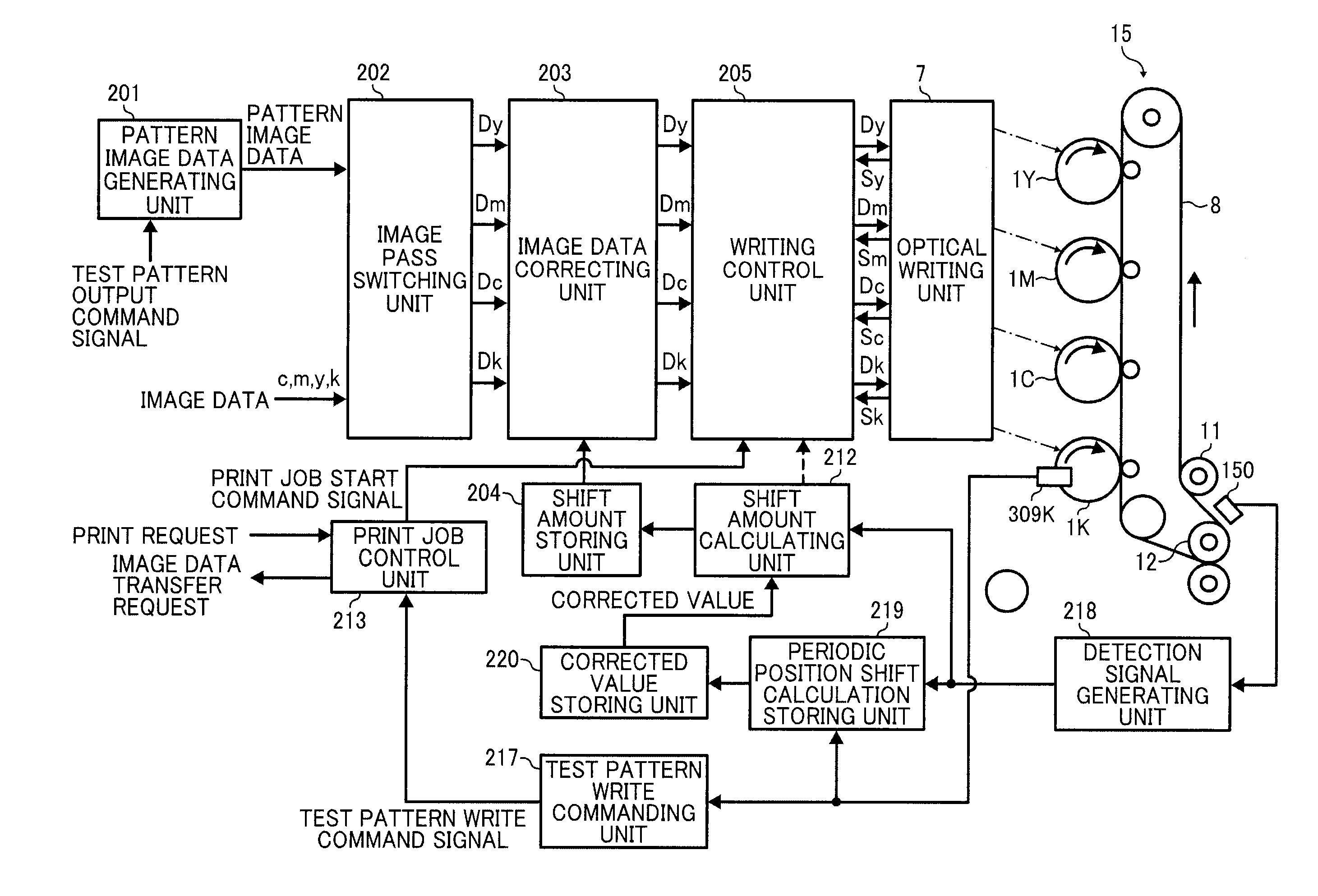
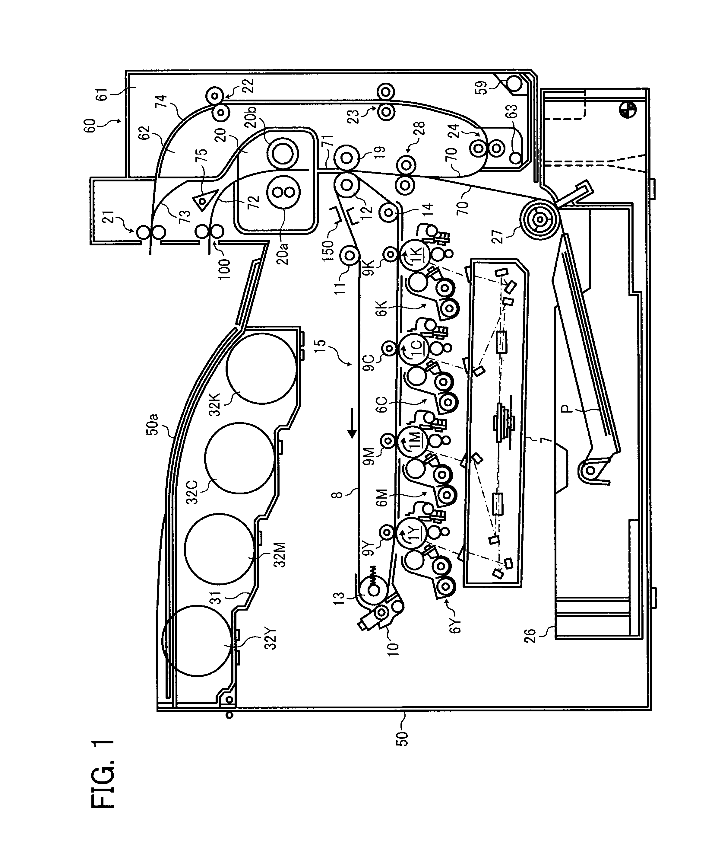
[0202]FIG. 18 is an enlarged view illustrating a part of a driving system that rotates photoconductors for 1Y, 1M, 1C, and 1K of the image forming apparatus of the first embodiment. In the image forming apparatus of the first embodiment, there is no relay gear that relays driving between the C photoconductor gear 302C and the K photoconductor gear 302K. So, if the driving gear 305 rotates located between the M photoconductor gear 302M and the C photoconductor gear 302C, that driving force is not conveyed to the K photoconductor gear 302K. The K photoconductor gear 302K engages with a second driving gear 308 that drives the K photoconductor gear 302K dedicatedly, and the second driving gear 308 is fixed to axis of a motor different from the motor connected to the driving gear 305. That is, in the image forming apparatus of the first embodiment, while the Y, M, and C photoconductors 1Y, 1M, and 1C are driven by one motor (hereinafter referred to as color photoconductor motor), the K p...
second embodiment
[0207]If any of photoconductor gears 302Y, 302M, 302C, and 302K is replaced, periodic position shift variation curve of the color is different from the one before the replacement, since eccentricity amount and eccentricity position of the replaced gear are different from the previous gear. Nevertheless, if periodic position deviation amount is figured out by using periodic position shift variation curve of the photoconductor gear before the replacement, some error is put out from the actual periodic position deviation amount and it is difficult to reduce color misalignment due to periodic position shift.
[0208]To cope with this issue, in the image forming apparatus of the second embodiment, measuring process of periodic position shift to measure periodic position deviation amount after replacement of gear for each color of Y, M, C, and K is executed based on a user's operation.
[0209]FIG. 19 is a diagram illustrating the Y, M, C, and K photoconductors 1Y, 1M, 1C, and 1K and the transf...
third embodiment
[0226]In the image forming apparatus of the third embodiment, measuring process of periodic position shift to measure periodic position deviation amount after replacement of gear for each color of Y, M, C, and K is also executed based on a user's operation. The difference from the second embodiment is number of formed periodic shift detecting pattern image Ipc formed in the periodic position shift measuring process and formed position for each color.
[0227]FIG. 26 is a diagram illustrating various periodic shift detecting pattern images Ipc formed in the periodic position shift measuring process with the intermediate transferring belt 8 in the image forming apparatus of the third embodiment. In the image forming apparatus of the third embodiment, three periodic misalignment detecting pattern images Ipc are formed for each color in the periodic position shift measuring process. The three periodic misalignment detecting pattern images Ipc for the same color is laid out sequentially in ...
PUM
 Abstract
Description
Claims
Application Information
 - R&D
- Intellectual Property
- Life Sciences
- Materials
- Tech Scout
- Unparalleled Data Quality
- Higher Quality Content
- 60% Fewer Hallucinations
Browse by: Latest US Patents, China's latest patents, Technical Efficacy Thesaurus, Application Domain, Technology Topic, Popular Technical Reports.
© 2025 PatSnap. All rights reserved.Legal|Privacy policy|Modern Slavery Act Transparency Statement|Sitemap|About US| Contact US: help@patsnap.com


