
Driving assembly for photosensitive drum, photosensitive drum assembly, process cartridge, and image forming apparatus

a technology of photosensitive drums and drive parts, which is applied in the direction of electrographic process equipment, instruments, optics, etc., can solve the problems of difficult to achieve exact performance during the expected lifespan, the point contact portion of the twisted protrusion may be easily abraded or damaged, and the typical technology described is limited. , to achieve the effect of easy abraded or damaged

Inactive Publication Date: 2013-03-07
BAIKSAN OPC +1
View PDF4 Cites 3 Cited by
  • Summary
  • Abstract
  • Description
  • Claims
  • Application Information

AI Technical Summary

Benefits of technology

The present invention provides a photosensitive drum driving assembly and process cartridge that allows for stable and smooth transmission of a driving force from the image forming apparatus to maintain stable image quality. Additionally, the invention includes a driving assembly and process cartridge that allows for easy insertion of the photosensitive drum assembly into the image forming apparatus. The invention also provides a driving assembly and process cartridge that prevents abrasions or damage to the photosensitive drum by improving the connection between the driving force and the photosensitive drum. These technical effects improve the overall performance and reliability of the image forming apparatus.

Problems solved by technology

However, there is the following limitation in the typical technology described above.
Accordingly, the contact point is easily abraded or damaged, making it difficult to achieve exact performance during the expected lifespan.
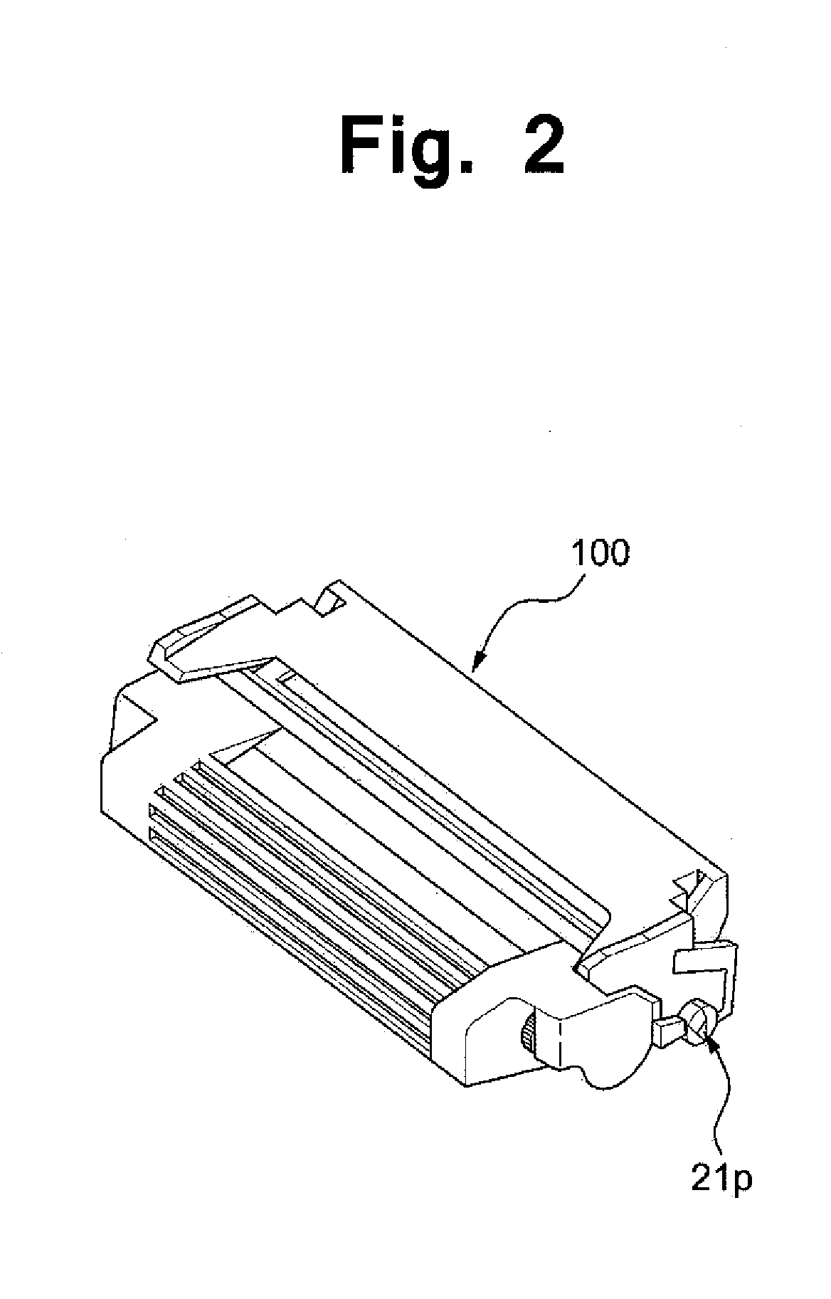
Due to such repetitive load, the point contact portion of the twisted protrusion 21p may be easily abraded or damaged.
When the point contact portion of the twisted protrusion 21p is abraded or damaged, the rotation precision is reduced upon rotation of the photosensitive drum, making it difficult to maintaining the concentricity of the drive shaft 180 and the photosensitive drum 10.

Method used


Image

  • Driving assembly for photosensitive drum, photosensitive drum assembly, process cartridge, and image forming apparatus
  • Driving assembly for photosensitive drum, photosensitive drum assembly, process cartridge, and image forming apparatus
  • Driving assembly for photosensitive drum, photosensitive drum assembly, process cartridge, and image forming apparatus

Examples


first embodiment

[0065]Referring to FIGS. 6 through 10B, a photosensitive drum assembly 100 according to the present invention may include a photosensitive drum 110 and a driving assembly 120 disposed on the photosensitive combination 120, and may be coupled to a drive shaft 180 rotating in a main body 2 of an image forming apparatus to receive a rotary force.

[0066]The driving assembly 120 may include a supporting body 122 combined at one side of the photosensitive drum 110, an engaging protrusion 121 protruding from the supporting body 122 so as to have a certain section and inserted into a triangular twisted hole 181, and a gear part 123 receiving a rotary driving force from the drive shaft 180 to rotate and delivering the rotary force to a development unit.

[0067]Specifically, a twisted contact surface S may be provided on the engaging protrusion 121 inserted into and engaging with the triangular twisted hole 181 to be in surface contact with on a twisted surface 181 s the triangular twisted hole ...

second embodiment

[0081]Hereinafter, the present invention will be described in detail with reference to FIGS. 11 through 13.

[0082]A photosensitive drum assembly 220 according to a second embodiment of the present invention differs from the first embodiment in that a contact expansion region dc in which the length of a line contact portion 221s with a twisted hole 181 become longer as getting closer to a base B from a front end E of an engaging protrusion 221 is formed. Accordingly, configurations of the second embodiment similar to those of the first embodiment will be indicated as the same or similar reference numerals, and detailed descriptions thereof will be omitted to clarify the essential points of the second embodiment.

[0083]The engaging protrusion 221 according to the second embodiment of the present invention will be described in detail below. A section 221E at the front end E of the engaging protrusion 221 may be similar to those of the front ends E of the first embodiment and previous eng...

third embodiment

[0096]A photosensitive drum assembly 320 according to the present invention may have an engaging protrusion 321 with a smaller twisted contact surface S at the front end thereof by cutting a front end portion of the engaging protrusion 321 to form an inclination surface W2.

[0097]Similarly to the engaging protrusion 121 of the first embodiment, the driving assembly according to the third embodiment of the present invention may have inclination surfaces W1 and W2 that are formed by removing a portion of the twisted contact surface S such that the sectional area of the engaging protrusion 321 increases as getting closer to the base B from the front end E. A boundary at which the inclination degree of the inclination surfaces W1 and W2 is changed may be defined as an inflection line K. Thus, since the inclination degree of the inclination surfaces W1 and W2 rapidly increases at the front end portion thereof; an interference generated when the engaging protrusion 321 is inserted into the...


PUM


Abstract

Provided is a photosensitive drum driving assembly, a photosensitive drum assembly, a process cartridge, and an image forming apparatus. The driving assembly including a supporting body and an engaging protrusion is connected to a drive shaft having a triangular twisted hole to transfer a rotary driving force from an image forming apparatus. The engaging protrusion twistedly protrudes to be inserted into the twisted hole, and includes three or more line contact portions on its cross-section perpendicular to the protrusion direction. The line contact portions are in line-contact with the surface of the twisted hole, and at least one portion of a surface formed by continuously joining the line-contact portions along the protrusion direction is a twisted contact-surface to receive the rotary driving force transferred by the drive shaft.

Description

CROSS-REFERENCE TO RELATED APPLICATIONS[0001]This U.S. non-provisional patent application claims priority under 35 U.S.C. §119 of Korean Patent Application No. 10-2011-0034930, filed on Apr. 15, 2011, the entire contents of which are hereby incorporated by reference.BACKGROUND OF THE INVENTION[0002]The present invention disclosed herein relates to a photosensitive drum driving assembly for receiving a driving force provided from a main body of an image forming apparatus, a photosensitive drum assembly, a process cartridge, and the image forming apparatus, and more particularly, to a photosensitive drum driving assembly and a photosensitive drum assembly, a process cartridge, and an image forming apparatus, which can rotate a photosensitive drum while minimizing a loss of a driving force provided from a main body of an image forming apparatus and can ensure a reliable and longer lifespan.[0003]Generally, examples of image forming apparatuses, which print characters or images on recor...

Claims


Application Information

Patent Timeline
IPC IPC(8): G03G15/00G03G21/18
CPCG03G15/757G03G15/00G03G21/18
Inventor LEE, BUM JINSEONG, CHANG RAEPARK, JANG SOON
Owner BAIKSAN OPC
Learn More