Digital speaker driving apparatus

a driving apparatus and digital speaker technology, applied in the direction of loudspeakers, transducers, instruments, etc., can solve the problems of increased cost, difficulty in lowering costs, and increased cost in reducing electromagnetic irradiation, so as to reduce the cost of the digital acoustic system, reduce the cost of the driving apparatus, and reduce the cost of the digital speaker. , the effect of low power consumption characteristics

Inactive Publication Date: 2013-03-07
TRIGENCE SEMICONDUCTOR INC
View PDF7 Cites 9 Cited by
  • Summary
  • Abstract
  • Description
  • Claims
  • Application Information

AI Technical Summary

Benefits of technology

The present invention allows for the creation of a digital acoustic system that is cheaper and more efficient than traditional analog systems. A combination of simple equipment can be used, and a low driving voltage is required for the digital speaker, meaning a large sound pressure can be achieved with low power consumption. The system does not require special semiconductor technology for handling high voltage, reducing costs. Additionally, the invention reduces electromagnetic irradiation that can affect sound quality, as the driving voltage is low. There is no A / D or D / A convertor between the digital signal source and the digital speaker, which also contributes to the improved sound quality.

Problems solved by technology

However, because it is presumed that an analog signal is input in a conventional speaker apparatus, it is necessary to convert the input analog signal into a digital signal in order to integrate a digital speaker apparatus into a conventional digital acoustic system, a significant problem arises when realizing a digital acoustic system which uses a digital speaker apparatus.
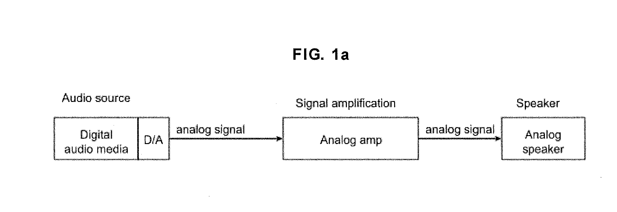
It is a more complex system compared with FIG. 1a, however, the digital amplitude amplification (D-class amplification) has higher power efficiency and the amplifier can operate with less power and with smaller space compared to an analog amplifier and therefore has become gradually used in recent years.
In FIG. 1b and FIG. 1c, after the amplitude is digitally amplified (D-class amplification), a signal is converted to an analog signal by a D / A convertor (usually an LC filter) and input to an analog speaker apparatus, however, the digital amplitude amplification must be done with a high voltage in order to output a large sound pressure, a digital amplitude amplification semiconductor device which uses a high voltage special semiconductor technology is required and it is difficult to lower costs.
In addition, when digital amplitude amplification is performed with a high voltage, electromagnetic irradiation becomes large and additional costs are incurred in order to reduce this electromagnetic irradiation.
In addition, there is a problem in which a deterioration in sound quality between an analog signal and a digital signal in the A / D (D / A) convertor between the digital signal source and the digital speaker apparatus can not be avoided.

Method used


Image

  • Digital speaker driving apparatus
  • Digital speaker driving apparatus
  • Digital speaker driving apparatus

Examples


second embodiment

[0079]FIG. 2b shows a second embodiment of a digital speaker apparatus system including a circuit which outputs a plurality of digital signals by a ΔΣ modulator and a post filter circuit, and a plurality of speaker driving elements. In the present embodiment, in order to adjust the volume of a digital speaker, the volume is digitally adjusted from a 1 bit digital input signal (210) input to the digital speaker apparatus, even though the regulator circuit (252a) which supplies a power for the speaker driving circuits (2031-203s) is not equipped with a means (254) for varying a supply voltage.

third embodiment

[0080]FIG. 2c shows a third embodiment of a digital speaker apparatus system including a circuit which outputs a plurality of digital signals by a ΔΣ modulator and a post filter circuit, and a plurality of speaker driving elements. In the present embodiment, in order to adjust the volume of a digital speaker, the volume is digitally adjusted based on information of a 1 bit digital input signal (210) input to the digital speaker apparatus, as a means (210) for varying a supply voltage of the regulator circuit (252a) which supplies a power for the speaker driving circuits (2031-203s).

[0081]When each of the speaker driving circuits (2031-203s), which are shown in FIG. 2a to FIG. 2c, is 2-valued (−1, 1), it is possible to have s+1 levels as a digital speaker driving state. In this case, m=s and the relationship 2n>(s+1) is satisfied in the ΔΣ modulator. An embodiment of a speaker driving circuit (300a) which has a 2-valued driving state is shown in FIG. 3a. Two types of switch circuit i...

fourth embodiment

[0085]A fourth embodiment of a digital speaker apparatus including a ΔΣ modulator, a post filter circuit, a plurality of speaker driving circuits and driving elements is shown in FIG. 4a (a back surface view) and FIG. 4b (side surface view) as an embodiment of a system including a digital speaker driving apparatus (400), which is formed with a ΔΣ modulator and a post filter circuit as one unit formed on a semiconductor or sealed in the same package, and a digital speaker apparatus (402) including a plurality of speaker driving elements. A 1 bit digital input signal (403) is input into the digital speaker driving apparatus (402) housing the ΔΣ modulator, the post filter circuit, the driving circuit of a plurality of digital signals, and a plurality of digital speaker driving signals (401) are output. A power supply line (404) supplies a power to the digital speaker driving circuit (402). The digitals speaker driving circuit (402) is arranged near the speaker driving elements so that ...


PUM


Abstract

A digital sound system suitable for a digital speaker device to directly convert analog sound by a circuit using a ΔΣ modulator and a mismatch shaping filter circuit to output a plurality of digital signals and a plurality of speakers driven by the plurality of digital signals. A digital speaker driving device includes a ΔΣ modulator, a post filter, s driving circuits, and a power supply circuit to supply power to the ΔΣ modulator, the post filter and the s driving elements, and the s driving circuits are adapted to s digital signal terminals.

Description

CROSS-REFERENCE TO RELATED APPLICATIONS[0001]This application is a continuation of and claims priority benefit to U.S. patent application Ser. No. 12 / 659,813, filed Mar. 22, 2010, allowed, which application in turn is a continuation based on and claims priority benefit to PCT Application No. PCT / JP2009 / 059867, filed on May 29, 2009, that application in turn claiming foreign priority benefit from prior Japanese Patent Application No. 2008-156284, filed on Jun. 16, 2008, Japanese Patent Application No. 2008-314438, filed on Dec. 10, 2008, Japanese Patent Application No. 2008-314905, filed on Dec. 10, 2008, and Japanese Patent Application No. 2008-314929, filed on Dec. 10, 2008, the entire contents of which are incorporated herein by reference.BACKGROUND[0002]1. Field[0003]The present invention is related to a digital speaker driving apparatus, a digital speaker apparatus, an actuator, a flat display apparatus, and a mobile electronic device. Specifically, the present invention is rela...

Claims


Application Information

Patent Timeline
Patent Type & Authority Applications(United States)
IPC IPC(8): H04B15/00G10L19/00
CPCH04R1/005H04R1/1008H04R3/12H04R2499/15H04R27/00H04R2227/003H04R2499/13H04R15/00H04R9/02H04R9/06H04R2400/11H04R2430/00H03F3/211H03F3/217H04R3/00
Inventor OKAMURA, JUN-ICHIYASUDA, AKIRA
Owner TRIGENCE SEMICONDUCTOR INC
Why Eureka
Try Eureka