Precise hip component positioning for hip replacement surgery
a hip joint replacement and component technology, applied in the field of minimally invasive surgical techniques, can solve the problems of unreliable computer guidance system total cost, unreliable traditional techniques for determining the proper positioning of the acetabular cup or femoral component,
- Summary
- Abstract
- Description
- Claims
- Application Information
AI Technical Summary
Benefits of technology
Problems solved by technology
Method used
Image
Examples
example 1
[0099]Generally, when using an acetabular component placement tool 300, start with the “Best Guess” approach (using the traditional “Sighting” Guide approach, plus the Cup Holder / Alignment Guide), obtain a radiographic or fluoroscopic image, and then use one embodiment of the present invention to make precise adjustments.
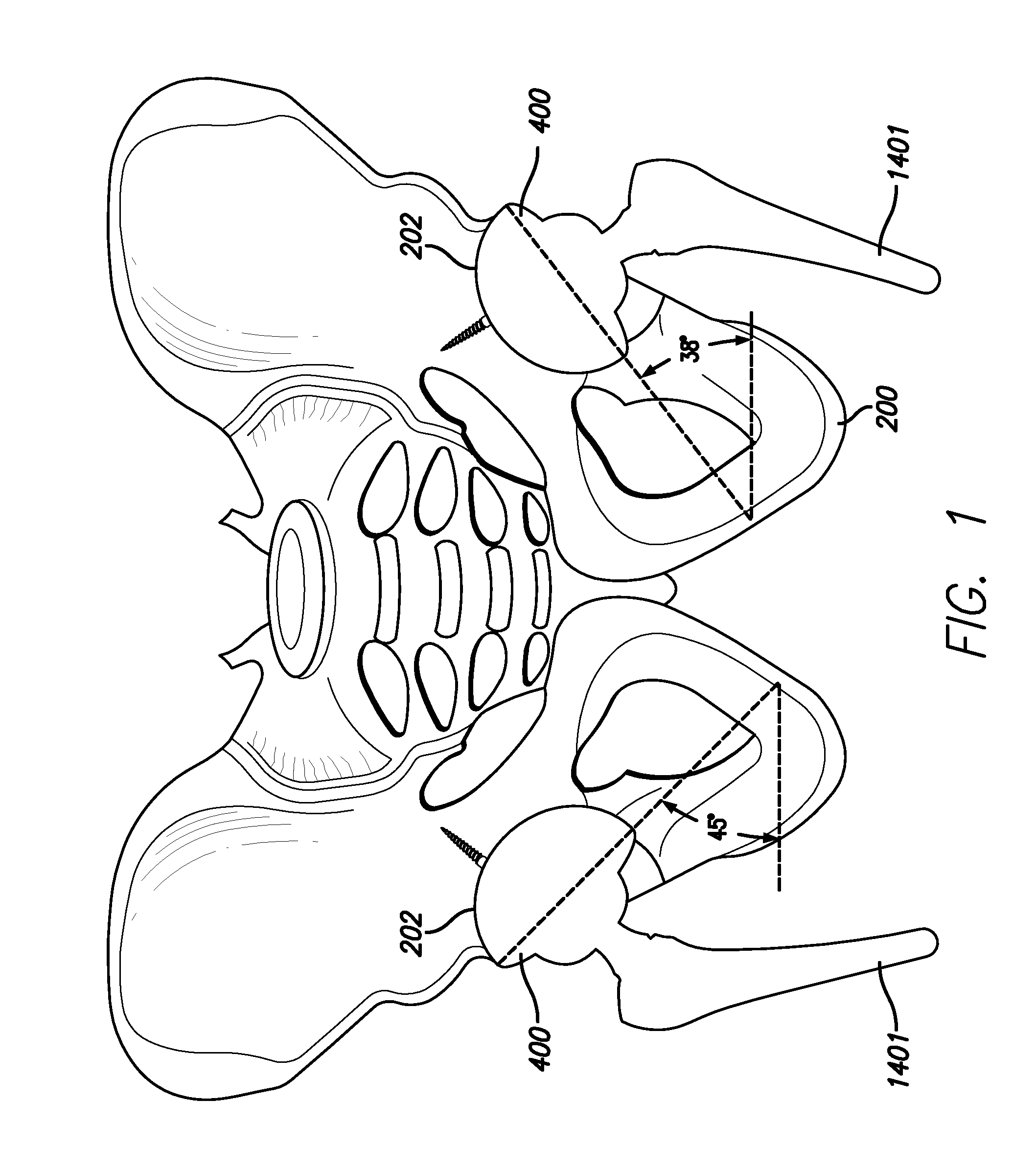
[0100]For example, once all of the proper incisions have been made and the acetabular components 400 is initially put in place with an acetabular component placement tool 300, the present settings of abduction and anteversion are read from the gyroscopic device 402. An imaging device 804, such as those used in radiographic or fluoroscopic imaging, can be used to create a radiographic or fluoroscopic image. For example, the imaging device 804 may be an x-ray machine emitting x-rays 806. From the radiographic imaging, the degree of abduction and anteversion needed for proper placement of the acetabular component 400 can be determined. Then, as the acetabular component...
example 2
[0102]In yet another embodiment, the best guess position can be made more precise by applying the present invention to the standard cup holder / alignment guide and, rather than relying on line of sight, i.e., identifying a neutral or zeroing orientation that at present is simply “sighted” in relation to operating room structures (a corner of the room, a vertical line of tiles on the wall, or any nearby straight vertical object) or imprecise anatomical landmarks (patient's trunk, shoulder, opposite kidney). That is to say, that the gyroscopic indicator is capable of indicating true vertical for the upright part of the guide and true zero or neutral for anteversion. After cup placement in the orientation directed by the combined references of the present invention connected (physically or remotely) to the recently redesigned alignment guide, the guide is then removed. Screws or a trial liner may then be placed. A femoral trial may also be placed in the best guess position either before...
example 3
[0104]This example is similar to Example 1 above, but including an attached “gyrometer.” The reamer basket (not shown) itself can act as a surrogate for the acetabular component 400. The gyrometer 402 settings can then be noted, an x-ray taken, and any corrections identified by measuring angles on the x-ray. This could be considered a way of calibrating the gyrometer 402. When returned to the same position (as indicated by the subsequent gyrometer 402 readout), correct acetabular component 400 positioning is then achieved by placing the acetabular component 400 in position, which results in corrected gyrometer readings.
[0105]By using a digital gyroscopic unit, the surgeon can quantify the orientation in space of the acetabular component greatly improving on the “best guess” orientation in which the surgeon might otherwise eyeball the positioning. Clinical research to date (including, Rubash, et al.) confirms a 40% error rate with current “best guess” in which the surgeon does not us...
PUM
 Abstract
Description
Claims
Application Information
 - R&D
- Intellectual Property
- Life Sciences
- Materials
- Tech Scout
- Unparalleled Data Quality
- Higher Quality Content
- 60% Fewer Hallucinations
Browse by: Latest US Patents, China's latest patents, Technical Efficacy Thesaurus, Application Domain, Technology Topic, Popular Technical Reports.
© 2025 PatSnap. All rights reserved.Legal|Privacy policy|Modern Slavery Act Transparency Statement|Sitemap|About US| Contact US: help@patsnap.com


