
Material and equipment recovery system

a technology of material and equipment, applied in the direction of mining structure, earth drilling and mining, slitting machines, etc., can solve the problems of unprofitable process, inability to insert personnel, and inability to meet the needs of strip mining

Inactive Publication Date: 2013-02-28
LOGAN HYDRAULICS
View PDF10 Cites 10 Cited by
  • Summary
  • Abstract
  • Description
  • Claims
  • Application Information

AI Technical Summary

Benefits of technology

The patent describes a recovery vehicle that can be remotely operated and has a towing feature. This allows the recovery vehicle to tow a surface control station to a different location at a mine site. The recovery implement can be a scoop for coal or material recovery or a grapple, manipulator, cutter, or combination of these for equipment recovery. This provides total autonomy for the recovery system at the mine site.

Problems solved by technology

When the coal to overburden ratio falls below a certain ratio, the process becomes unprofitable and strip mining ceases to be the economically preferred technique at that location.
This is considered too dangerous for the insertion of any personnel and the cutter modules are directed and operated remotely.
Due to the cutter module design as well as other factors in the mining process, some percentage of the coal mined by the highwall miner ends up as spillage and is not recovered.
On occasions, components from the cutter modules become detached and are lost during the mining process.
At the present time, there is not a practical way of recovering these components, and the cutter module cannot continue to operate with the loose component in the cut.

Method used


Image

  • Material and equipment recovery system
  • Material and equipment recovery system
  • Material and equipment recovery system

Examples


Embodiment Construction

)

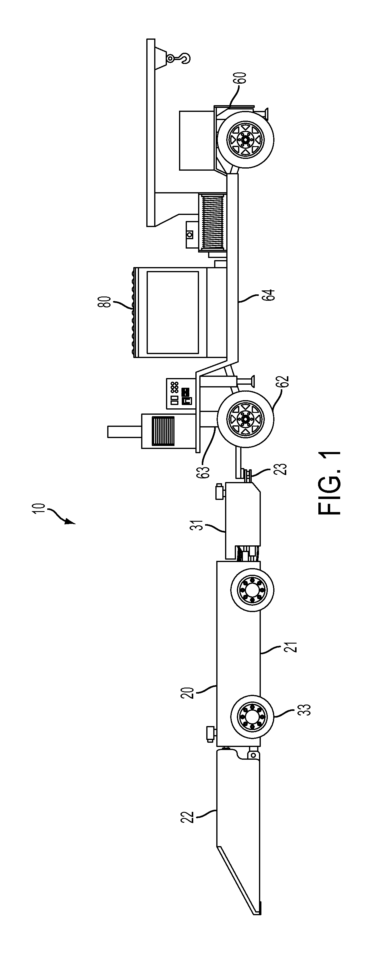
[0026]FIG. 1 is a perspective view of an embodiment of recovery system 10. In FIG. 1, recovery vehicle 20 is hitched to surface control station 60. In this embodiment, recovery vehicle 20 can hitch to surface control station 60 to move about a mine site. The ability of recovery system 10 to reposition itself about a mine site gives the system complete operational autonomy. In FIG. 1, recovery vehicle 20 tows fifth wheel dolly 62 and fifth wheel hitch 63 on surface control station 60 joins to fifth wheel dolly 62. Later figures provide more detail for recovery vehicle 20 and surface control station 60.

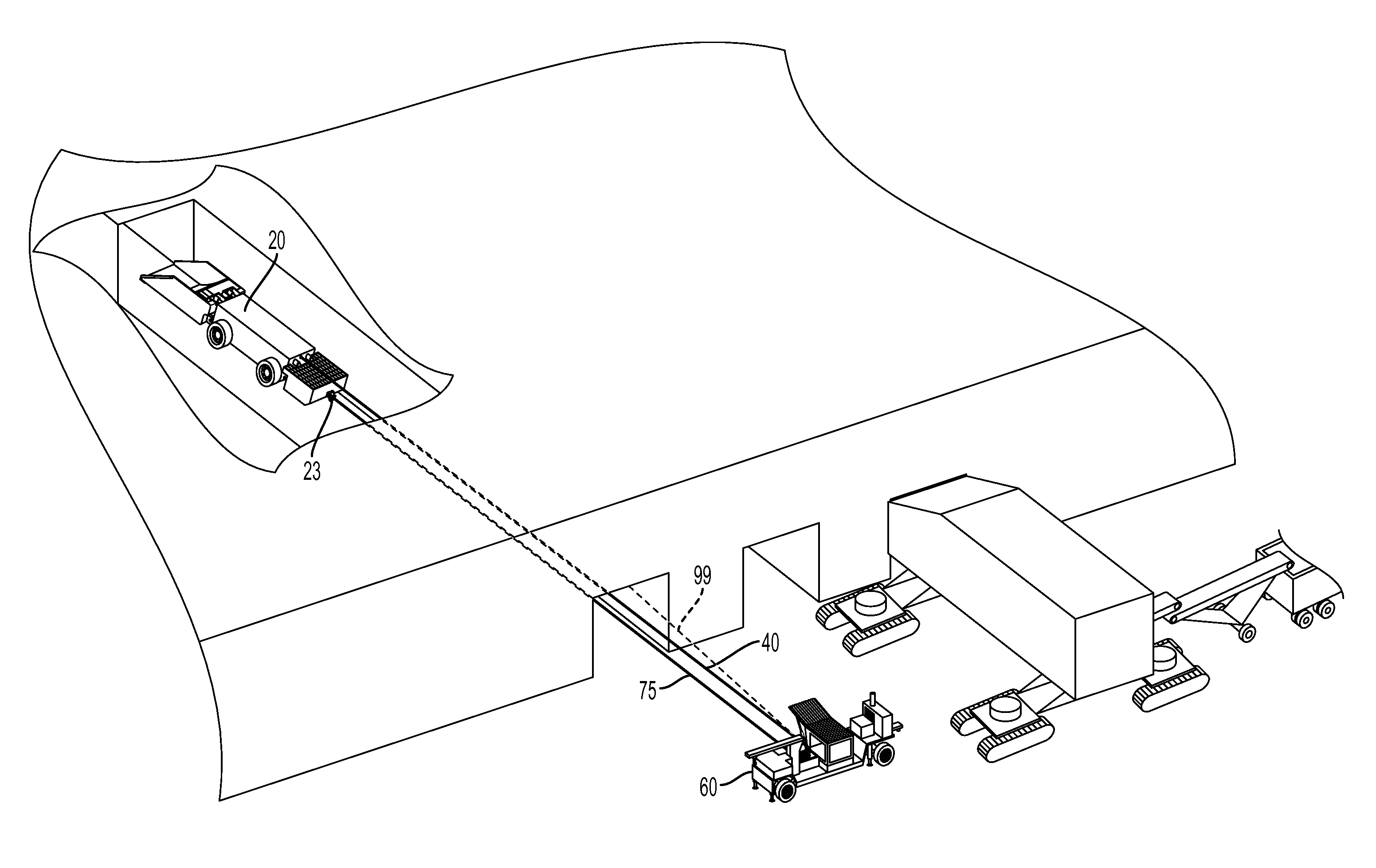
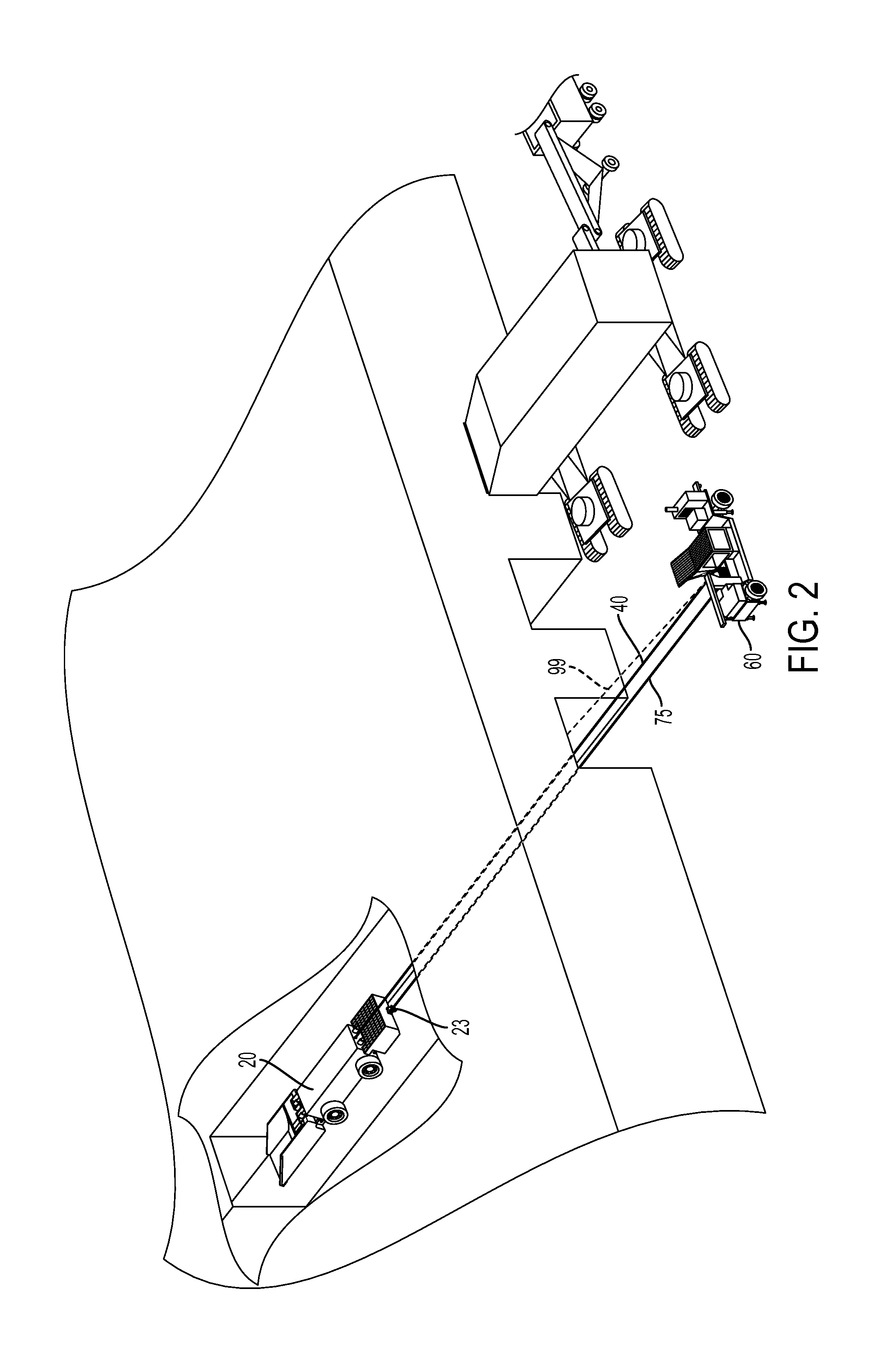
[0027]FIG. 2 shows recovery system 10 in location at a mine. Surface control station 60 is aligned with a cut previously made by a highwall miner. Recovery vehicle 20 is located within the cut and is operated from surface control station 60. Data cable 40 extends from surface control station 60 to recovery vehicle 20 to transmit control signals from surface control station 60 to recove...


PUM


Abstract

A material and equipment recovery system for high risk environments has a recovery vehicle and surface control station, and a communication link between them, which may be an Ethernet link. The recovery vehicle has an operable recovery implement suitable to its particular application. The surface control station has an operator station from which an operator can operate the recovery vehicle remotely. Cameras on the recovery vehicle provide images for an operator to maneuver the recovery vehicle and monitor systems on the recovery vehicle. The surface control station also has a winch and recovery cable that attaches to the recovery vehicle to retrieve it should it become disabled. An optical alignment device on the surface control station allows alignment of the surface control station to keep the retrieval cable effective. The recovery vehicle and control station have hitch elements and the recovery vehicle can reposition the control station at a site.

Description

RELATED APPLICATIONS[0001]This application claims priority from U.S. Provisional Application No. 61 / 528,200, filed on Aug. 27, 2011. The entire disclosure contained in U.S. Provisional Application 61 / 528,200, including the attachments thereto, is incorporated herein by reference.FIELD OF INVENTION[0002]The present application is generally related to material and equipment recovery. More specifically, the present application is related to material and equipment recovery in a high risk environment with an unmanned vehicle.BACKGROUND OF THE INVENTION[0003]One example of an application for the apparatus of the present invention is highwall mining. During the past forty years, highwall mining has proven to be an efficient method of mining coal, or other sought after material, that would not be mined by other methods. Highwall mining is a form of mining frequently used to supplement strip mining.[0004]Strip mining is used when the sought after material deposits, such as coal, occur relati...

Claims


Application Information

Patent Timeline
Patent Type & Authority Applications(United States)
IPC IPC(8): E21C35/20
CPCE21C27/24E21F11/00E21F13/006E21C35/24E21F13/02
Inventor GRAHAM, ROBERT WAYNE
Owner LOGAN HYDRAULICS
Learn More