
Back pressured hydraulic pump for sucker rod

a hydraulic pump and sucker rod technology, applied in machines/engines, positive displacement liquid engines, borehole/well accessories, etc., can solve the problems of limiting the overall stroke rate, limiting the maximum permissible for certain well applications, and generally non-adjustable sinusoidal velocity profiles of sucker rod strings, etc., to achieve equal or superior efficiencies

Active Publication Date: 2013-02-21
DOWNHOLE WATER MANAGEMENT
View PDF14 Cites 13 Cited by
  • Summary
  • Abstract
  • Description
  • Claims
  • Application Information

AI Technical Summary

Benefits of technology

The patent describes a hydraulic system for actuating a well sucker rod. This system offers superior efficiency to a mechanical system and allows for unrestricted control over the sucker rod's velocity profile. It also records measurements and enables quick identification and correction of downhole problems. The system includes a hydraulic cylinder assembly, a punch load, a reversible hydraulic pump, a pressurized supply of hydraulic fluid, and a control system. The control system causes hydraulic fluid to flow back and forth between the cylinder and the pressurized supply. This reduces the energy needed to raise and lower the load. The system allows for easy assembly at ground level and quick lowering for access to wells.

Problems solved by technology

One of the drawbacks of this arrangement is that the sucker rod string follows a generally nonadjustable sinusoidal velocity profile.
Certain well applications may be limited by a maximum permissible upstroke and / or downstroke velocity.
When coupled with the fixed sinusoidal motion of the rocking beam, the velocity limitation constrains the overall stroke rate, and therefore the overall well production rate.
However, the addition of another cylinder to the system reduces reliability, often increases overall height, and increases system complexity.
An additional shortcoming of both existing prior art hydraulic and mechanical systems is that no means are provided for diagnosing the development of problems downhole.
For example, failure of the pump, leakage in the pump, changes in the liquid makeup in the well, dry bottom conditions in the well, excessive sucker rod drag, will all manifest themselves by changes over time in the work increments being done by the unit.

Method used


Image

  • Back pressured hydraulic pump for sucker rod
  • Back pressured hydraulic pump for sucker rod
  • Back pressured hydraulic pump for sucker rod

Examples


Embodiment Construction

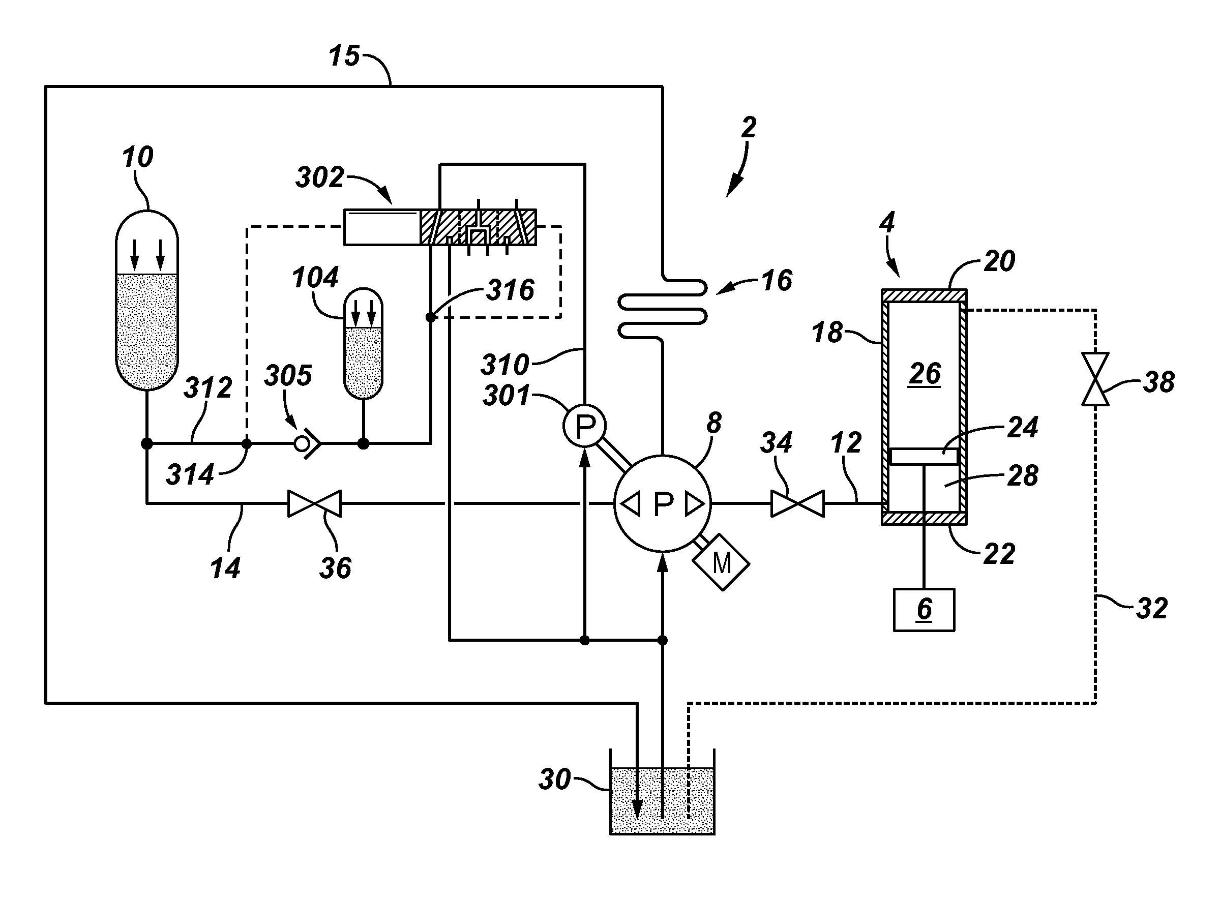
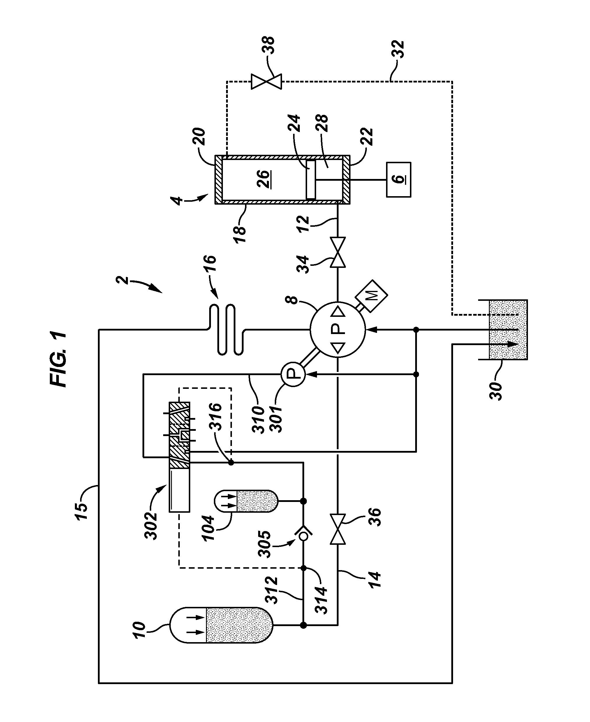
[0034]With reference to FIG. 1, there is shown schematically an apparatus 2 comprising a hydraulic cylinder assembly 4, a load 6 connected to the cylinder assembly, a reversible hydraulic pump assembly 8, a pressurized supply 10 of hydraulic fluid, a first conduit for hydraulic fluid 12, and a second conduit for hydraulic fluid 14. FIG. 7 further shows schematically a control system 17 for the unit. The hydraulic cylinder assembly, detailed in FIG. 9, comprises a cylinder 18 sealed by an upper head 20 and a lower head 22 and carrying a piston 24 which divides the hydraulic cylinder assembly into an upper chamber 26 and a lower chamber 28. The load is connected to the piston and urges it toward the lower head. See FIG. 1. The first conduit for hydraulic fluid connects the reversible hydraulic pump assembly in fluid flow communication with the lower chamber of the hydraulic cylinder assembly. The second conduit for hydraulic fluid connects the reversible hydraulic pump assembly in flu...


PUM


Abstract

A hydraulic pump includes a hydraulic cylinder assembly comprising a cylinder sealed by an upper head and a lower head and carrying a piston which divides the hydraulic cylinder assembly into an upper chamber and a lower chamber. A load is connected to the piston and urges it toward the lower head. A conduit connects a reversible hydraulic pump assembly in fluid flow communication with a pressurized supply of hydraulic fluid and the lower chamber for counterbalancing the load. A control system is operably associated with the reversible hydraulic pump assembly to cause hydraulic fluid to flow back and forth between the lower chamber of the hydraulic cylinder assembly and the pressurized supply of hydraulic fluid. A system is also provided to counteract leakage in the pump by adding hydraulic fluid makeup on an as needed and controlled basis.

Description

CROSS REFERENCES TO RELATED APPLICATIONS[0001]This application is a division of application Ser. No. 12 / 803,478 filed Jun. 28, 2010, now ______, which was a continuation-in-part of application Ser. No. 11 / 985,776, filed Nov. 17, 2007, now abandoned, which claimed the benefit of U.S. Provisional Application No.: 60 / 859,676 filed Nov. 17, 2006. The disclosures of these earlier filed applications are incorporated by reference herein.FIELD OF THE INVENTION[0002]In certain embodiments, the invention relates to a method and apparatus for operating a hydraulic cylinder to actuate a downhole pump coupled to the cylinder via a sucker rod linkage. In one aspect, the invention relates to a derrick useful for oil and gas operations.BACKGROUND OF THE INVENTION[0003]Mechanical pump jacks have been used for many years in the oil and gas industry to remove liquids from deep wells. Typically, a rocking beam is connected at one end to a string of sucker rods which actuates a downhole pump mechanism a...

Claims


Application Information

Patent Timeline
Patent Type & Authority Applications(United States)
IPC IPC(8): E21B43/00E04H12/34
CPCF04B47/04
Inventor RAMSEY, MICHAEL C.FINLEY, MICHAEL L.
Owner DOWNHOLE WATER MANAGEMENT
Learn More