
Method and Apparatus for Separation of Impurities from Liquid by Upflow Granular Media Filters

a granular media filter and liquid separation technology, applied in the direction of filtration separation, moving filter element filter, separation process, etc., can solve the problems of unnecessarily increasing the cost of such a system, reducing the productivity of the system, and the inability of the filtration process to be continuous

Inactive Publication Date: 2013-02-14
JIANG HUA
View PDF7 Cites 4 Cited by
  • Summary
  • Abstract
  • Description
  • Claims
  • Application Information

AI Technical Summary

Benefits of technology

The patent text describes a continuous-backwashing filter that is not suitable for high quality water production due to its high cost and limited water quality requirements. The main technical effect of the filter is that it is difficult to maintain and repair, and uses complicated air as the transport mechanism for regeneration of the filter media which causes localized fluidization of the filter media. Other similar continuous filters have similar disadvantages.

Problems solved by technology

The disadvantage of a conventional filtration system is that the filtration process can not be continuous as the filer media has to be regenerated periodically.
This procedure reduces the productivity of the system.
Another disadvantage of the conventional filtration system is that in order to produce clean water continuously, at least one standby unit has to be provided and turned on while the active unit is being backwashed.
The installation of a standby unit increases the cost of such a system unnecessarily.
Additional disadvantage of the conventional filtration system discussed above is that a backwashing system has to be provided to perform the backwash.
The backwashing system adds extra expenses to the overall treatment system investment.
However it has its own serious drawbacks.
One major drawback of a filter described in U.S. Pat. Nos. 4,126,546 and 4,197,201 is that the washing device is inadequate for cleaning the filter media.
The effectiveness of this process is relatively poor.
The turbidity and concentration of suspended solids in the product water was high and could not meet the potable water standard established by United States Environmental Protection Agency (USEPA).
Using dual stage of such a filter as disclosed in U.S. Pat. Nos. 6,426,005 B1 and 5,843,308 severely limits its application in cases where high quality of water is required, such as potable water production, since such a system would require significantly higher investment and occupy doubled footprint.
Another drawback of a filter described in U.S. Pat. Nos. 4,126,546 and 4,197,201 is that the air-lift mechanism is insufficient to break up the binding between solids and filter media and results in elevated solid concentration in the treated water.
Using a stream of air in such a filter is unable to effectively break up the binding between the solid and the filter media and therefore adequately clean the media.
If the filter media are not cleaned adequately, it could lose its filtering capacity and it has to be cleaned more frequently in order to produce the water with the same quality.
Still another drawback of a filter described in U.S. Pat. Nos. 4,126,546 and 4,197,201 is that it is difficult to access the air-lift transport conduit for inspection, maintenance, or repair.
The transport conduit is subject to clogging and blockage due to the nature of the dirtied filter media.
Since the transport conduit is located inside the tank which is filled with the filter media, the filter media must be evacuated before one can inspect, maintain, or repair the transport conduit which increases the downtime and requires more labor.
One additional drawback of a filter described in U.S. Pat. Nos. 4,126,546 and 4,197,201 is that localized fluidization in the filer bed is inevitable as compressed air is utilized as the driving force to transport the dirtied sand for cleaning.
Although an air capture device was included, a portion of the air would inevitably escape into the tank and cause localized fluidization of the filter media.
Fluidization in a filter is undesirable as it could reduce the filtration efficiency of the filter media and results in higher concentration of solids and turbidity in the effluent.
Its application is limited in situations where the water quality requirement is low.
Using compressed air as the means of transportation makes the system complicated.

Method used


Image

  • Method and Apparatus for Separation of Impurities from Liquid by Upflow Granular Media Filters
  • Method and Apparatus for Separation of Impurities from Liquid by Upflow Granular Media Filters
  • Method and Apparatus for Separation of Impurities from Liquid by Upflow Granular Media Filters

Examples


Embodiment Construction

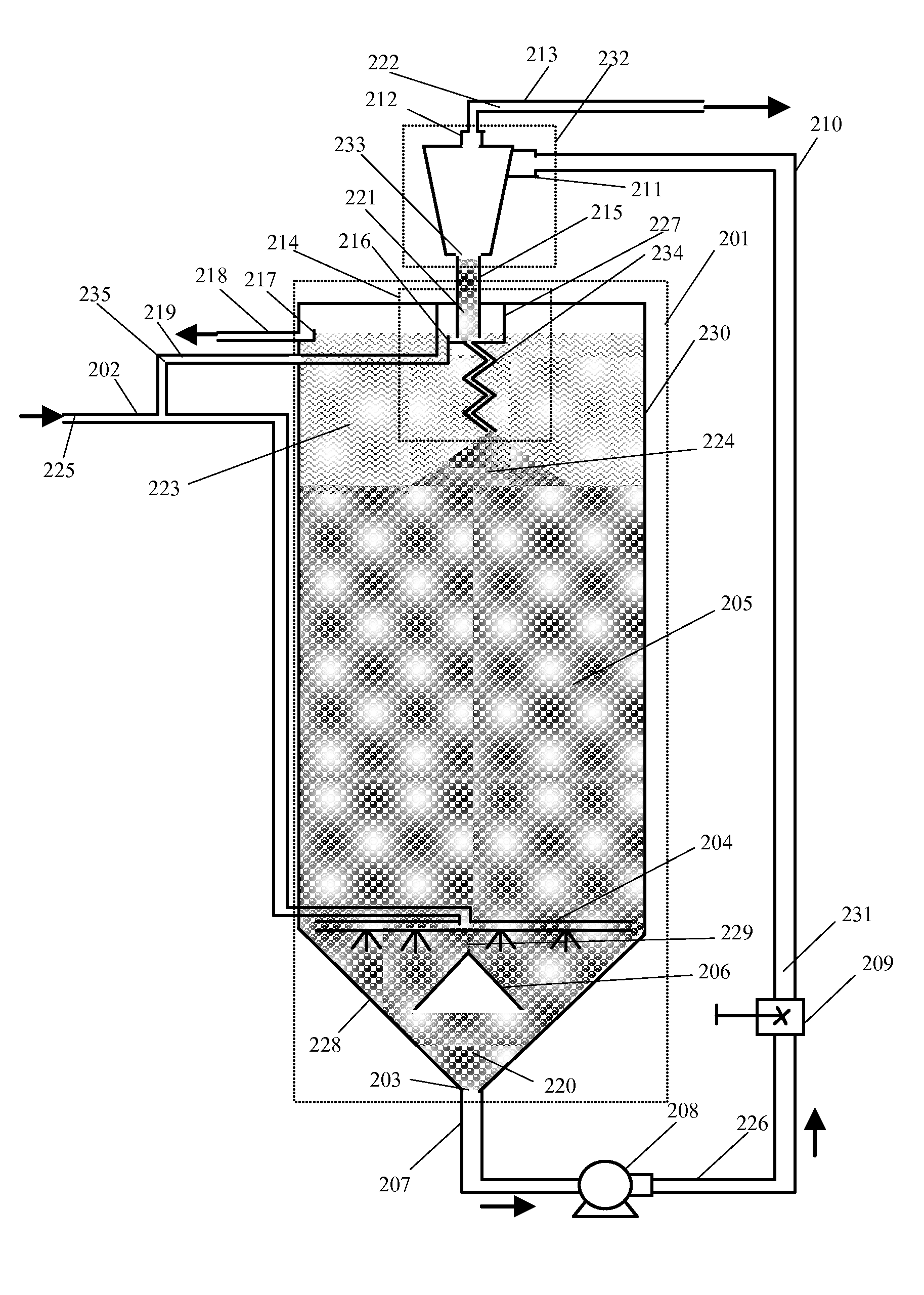
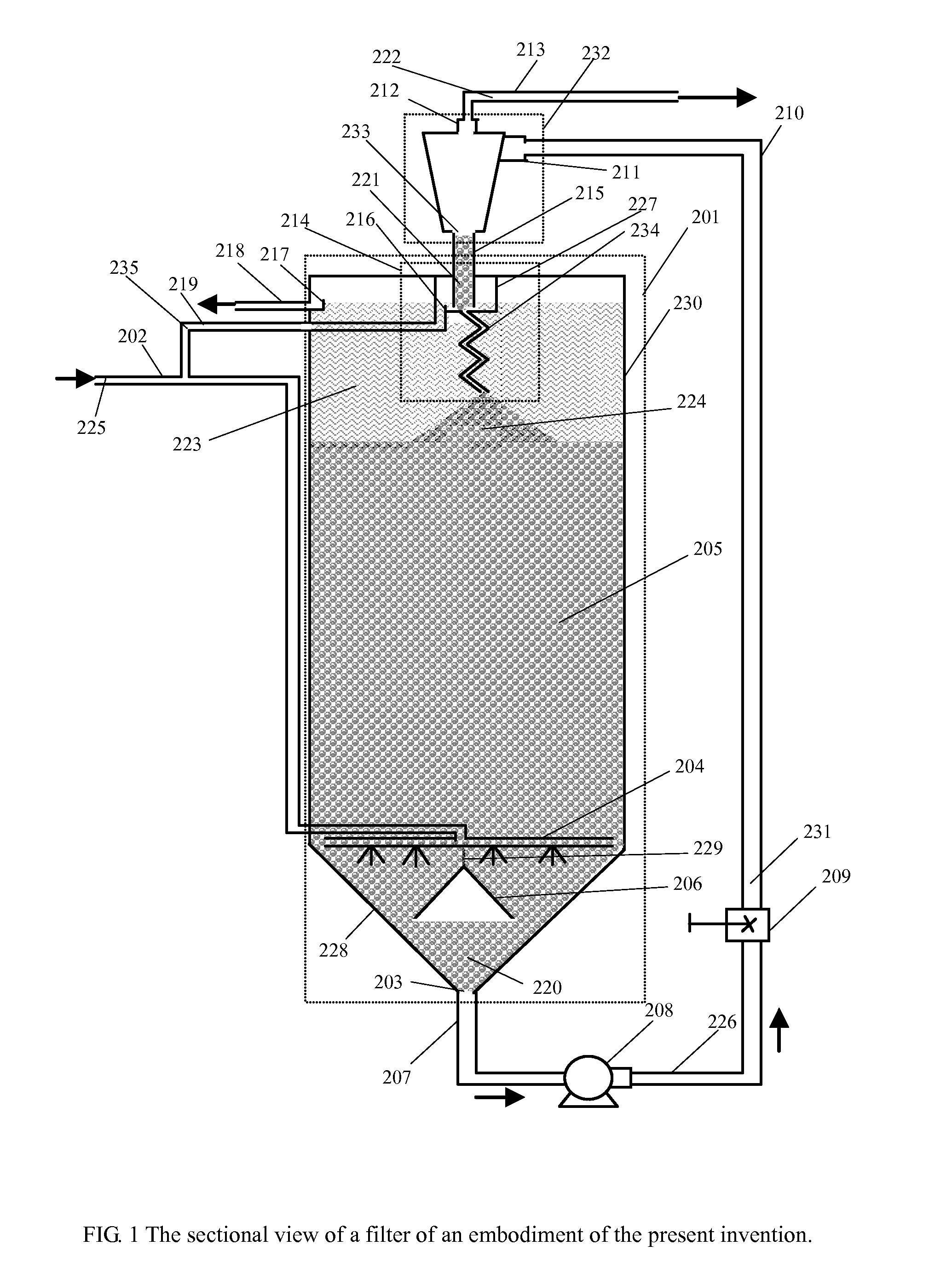
[0018]With reference to FIG. 1, a preferred embodiment of filter apparatus of this invention is presented.

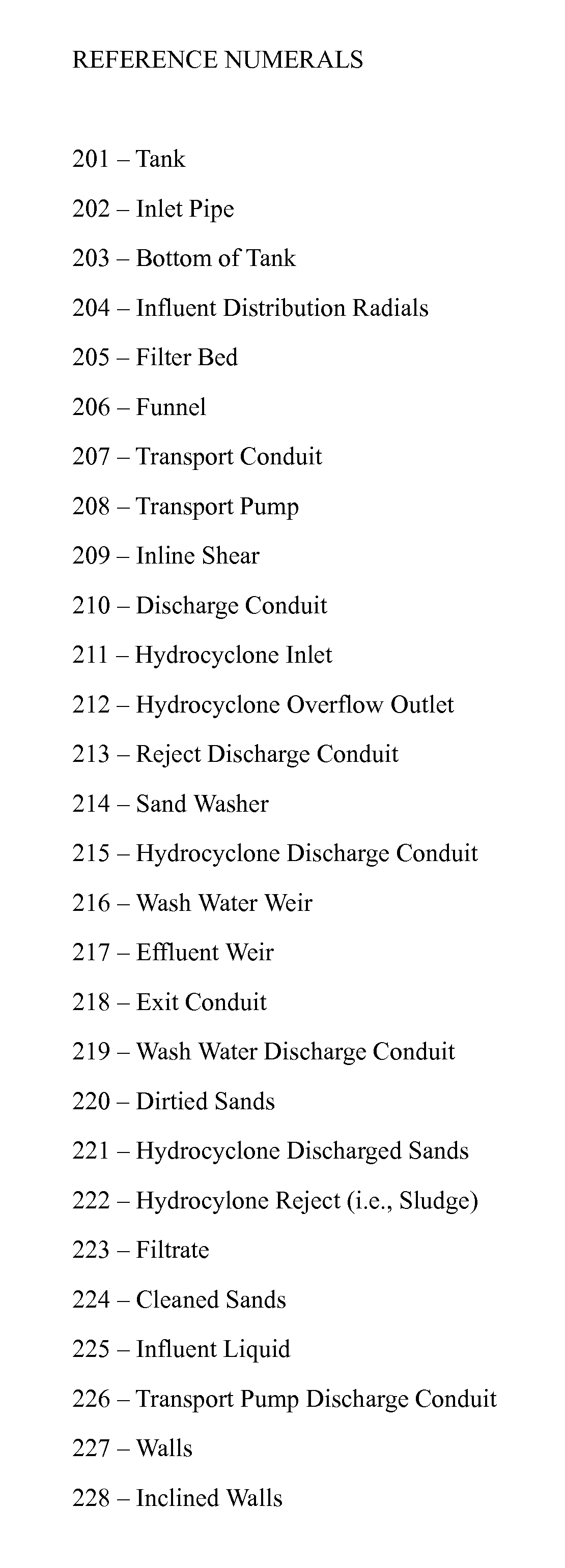
[0019]A tank 201 contains a filter bed 205 consisting of loose, granular filter media, preferably of uniform grain size. The tank 201 is defined by vertical walls 230 and conical or inclined walls 228 which form a funnel-shaped bottom. The filter media can consist of e.g. sand, sand and gravel, or any granular material having an absorptive surface structure (sand is used as the filter media as illustrative purpose here). Liquid 225, which can be water or any other liquids need to be filtered, enters through an inlet pipe 202. The inlet pipe 202 connects to a series of distribution radials (the radial rack) 204 which introduces the liquid 225 into the filter bed 205. The radial rack 204 is located concentrically at the vertical base of the filter bed and it ensures the liquid 225 is equally distributed within the filter bed 205. A funnel 206 is placed upside down and is connected...


PUM


Abstract

The present invention is a gravity continuously operating filtration system for separating impurities from liquids. The liquid flows upward through a bed of filter media in a vessel and filtered liquid (filtrate) is collected above the top of the bed. Dirtied filter media are withdrawn from the bottom of the vessel and returned to the vessel from the top. The dirtied filter media are first conveyed to a separation device by which the bulk of solids are separated from the filter media. The reject liquid from the separation device is discharged as waste. The filter media are then cleaned in a spiral wash path and are then returned back to the system. The described cleaning process is far more effective than other similar filtration systems. Majority of essential components are located outside of the vessel and are convenient to access for maintenance and inspection.

Description

BACKGROUND OF THE INVENTION[0001]1. Field of the Invention[0002]This relates to a method, an apparatus, and a system for the separation of impurities from liquid. In particular, the invention relates to an improved method and an improved apparatus to filter, but not limited to, suspended solids, from a liquid.[0003]2. Description of the Prior Art[0004]The conventional method to remove suspended solids from a liquid is to pass the liquid through a bed of granular media in a downward direction (i.e., from the top to the bottom.). When solids contacts with the granular media, they are retained by them and are therefore removed from the liquid. A device like this is called filter. Once the media are saturated with suspended solids, the filter must be shut down and the filtration process will be stopped to regenerate the media. This process is called backwash. The backwash process typically consists of dislodging solids by introducing a stream of air by itself or in combination with a st...

Claims


Application Information

Patent Timeline
IPC IPC(8): B01D24/46B03C1/30B01D24/32B01D37/00
CPCB01D24/4689B01D24/105
Inventor JIANG, HUA
Owner JIANG HUA
Learn More