Pneumatic radial tire

a radial tire and pneumatic technology, applied in the field of pneumatic radial tires, can solve the problems of causing separation, generating trouble at the beginning of the tread, and deteriorating durability, so as to increase the volume of high tensile stress layer, and enhance the effect of improving durability

Inactive Publication Date: 2013-02-14
TOYO TIRE & RUBBER CO LTD
View PDF5 Cites 15 Cited by
  • Summary
  • Abstract
  • Description
  • Claims
  • Application Information

AI Technical Summary

Benefits of technology

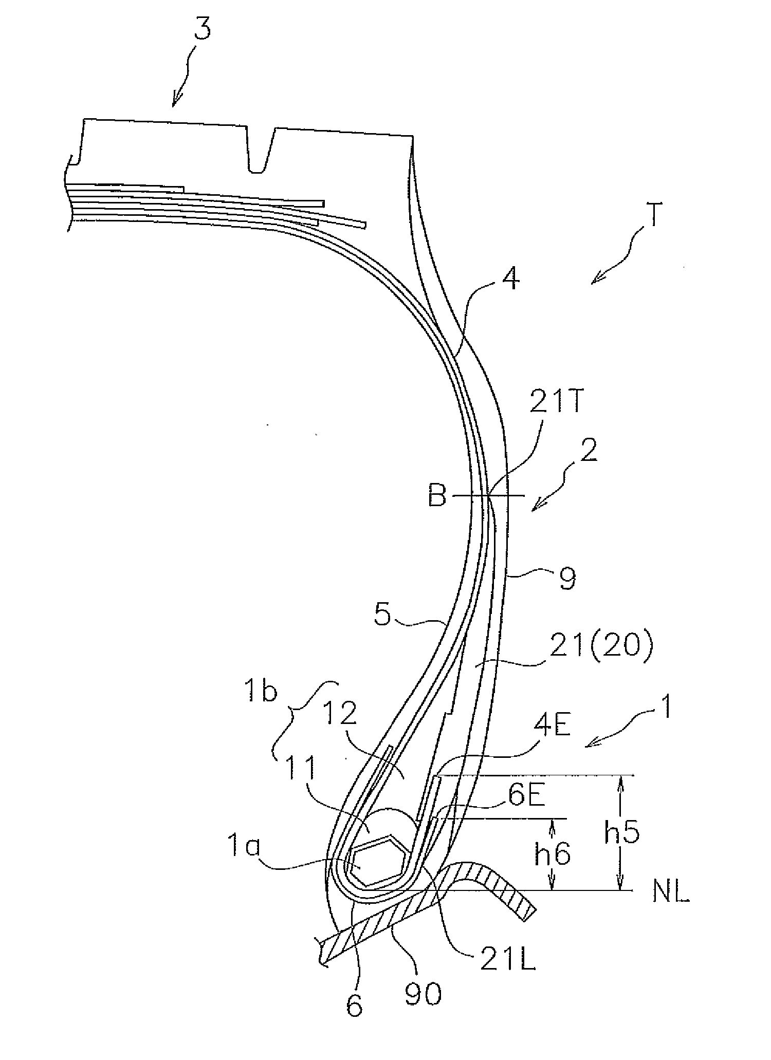
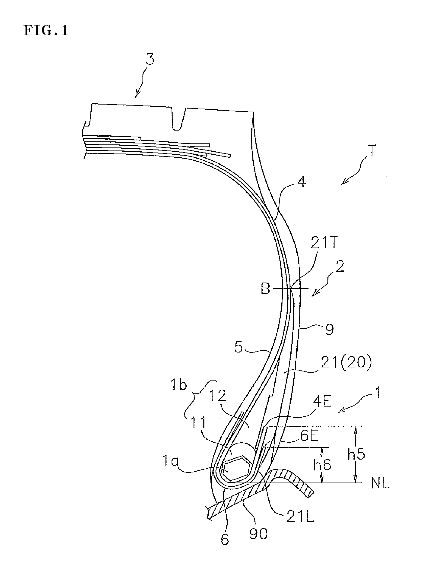
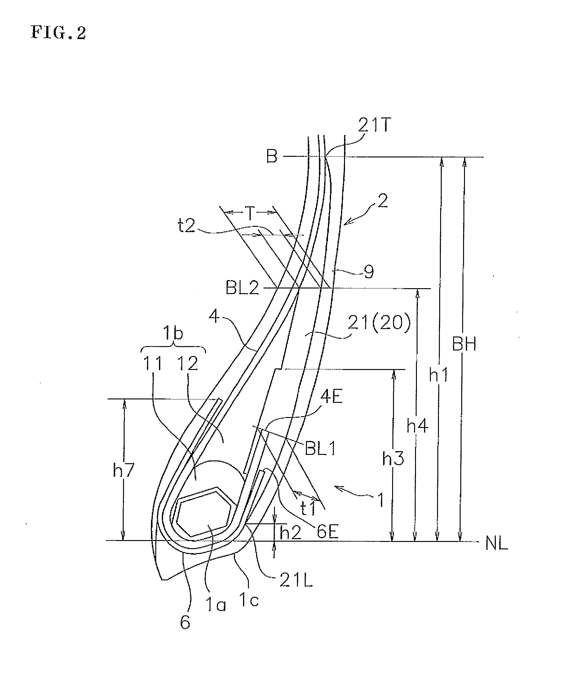
The present invention relates to a pneumatic radial tire that suppresses a protruding deformation of a bead portion during traveling and has enhanced durability. The tire comprises a reinforcing rubber layer positioned between the rubber filler and the side wall rubber, which consists of a monolithic layer that serves as a support post to suppress the protruding deformation of the bead portion. The monolithic layer has a predetermined elongation tensile stress between 1.6 MPa and 6.2 MPa to effectively suppress the protruding deformation and the occurrence of trouble beginning at the wind-up ends of the carcass ply and the chafer. Additionally, the tire also includes a high tensile stress layer positioned at a height to enhance durability, with an upper end at a height of 0.2 to 0.65 times the tire maximum width position based on the rim reference line.

Problems solved by technology

Conventionally, in a pneumatic radial tire which is particularly used in a vehicle having a heavy weight, such as an industrial vehicle or a construction vehicle, there has been fear that a trouble such as separation is caused from a wound-up end of a carcass ply wound up around a bead core.
However, even if the chafer is arranged, durability may deteriorate due to a protruding deformation of a bead portion, and there is a room for further improving this.
If the protruding deformation mentioned above is repeated in connection with a rolling motion of the tire, a great strain acts on a wind-up end 4E of a carcass ply and a wind-up end 6E of a chafer which topple toward an outer side, and a trouble beginning at them tends to be generated.

Method used


Image

  • Pneumatic radial tire
  • Pneumatic radial tire
  • Pneumatic radial tire

Examples


example

[0053]Since a durability test of the bead portion was carried out in order to specifically show the structure and the effect of the present invention, a description will be given below. A tire used for the test had a size of 11R22.5, and was installed to a rim having a size specified by JATMA.

[0054]In the durability test, under a condition of an internal pressure 900 kPa and a speed 40 km / h, the tire was traveled on a drum, a load was gradually increased from 230% in the JATMA normal condition, and a traveling distance at the time when the trouble occurred was evaluated. Accordingly, the longer traveling distance indicates excellent durability.

[0055]The bead structure and the result of evaluation in comparative examples 1 to 3 and working examples 1 to 4 are as shown in Table 1. The bead structures of the comparative examples 1 and 2 are respectively shown in FIGS. 6 and 7, and the reinforcing rubber is formed by the rubber material having the same composition as the upper filler in...


PUM


Abstract

A pneumatic radial tire has a carcass ply wound up around a bead core, a chafer wound up around the bead core to be arranged in an outer side of the carcass ply, and a side wall rubber. A reinforcing rubber is provided between a rubber filler and the side wall rubber to pinch a wind-up end of the carcass ply and a wind-up end of the chafer. The reinforcing rubber has a monolithic layer extending in a tire diametrical direction. An upper end of the monolithic layer is positioned at a height which is 0.9 to 1.1 times a height of a tire maximum width position based on a rim reference line. A lower end of the monolithic layer is positioned in an outer side of the chafer at a height within ±10 mm based on the rim reference line.

Description

BACKGROUND OF THE INVENTION[0001]1. Field of the Invention[0002]The present invention relates to a pneumatic radial tire which is characterized by a structure of a bead portion and has a high durability. The present invention is particularly useful for a pneumatic radial tire for a heavy load.[0003]2. Description of the Related Art[0004]Conventionally, in a pneumatic radial tire which is particularly used in a vehicle having a heavy weight, such as an industrial vehicle or a construction vehicle, there has been fear that a trouble such as separation is caused from a wound-up end of a carcass ply wound up around a bead core. Accordingly, it is generally carried out to intend an improvement of a durability of the bead portion by arranging a reinforcing member called a chafer along the carcass ply, as disclosed in Patent Documents 1 and 2. However, even if the chafer is arranged, durability may deteriorate due to a protruding deformation of a bead portion, and there is a room for furth...

Claims


Application Information

Patent Timeline
Patent Type & Authority Applications(United States)
IPC IPC(8): B60C15/06
CPCB60C15/0635B60C2015/0617B60C2015/061B60C15/0607
Inventor KODAMA, NORIHIKO
Owner TOYO TIRE & RUBBER CO LTD
Why Eureka
Try Eureka