
Channel lock filter fastening system for use with an air intake structure

a filter and air intake technology, applied in the field of channel lock construction, can solve the problems of increasing the cost of filters, significant effort and time, both mounting time and effort, and achieve the effect of quick installation

Inactive Publication Date: 2013-02-14
SIMMONS RANDY
View PDF3 Cites 15 Cited by
  • Summary
  • Abstract
  • Description
  • Claims
  • Application Information

AI Technical Summary

Benefits of technology

The present invention provides an improved channel supporting construction for installing any type of covering member, reducing the number of screw holes needed and avoiding sensitive regions on the equipment. The invention also allows for quicker self-alignment of fasteners to filter grommets, reducing installation time and effort and preventing mounting related wrinkling of the filter. The invention includes wing nuts for securely flattening screens against the intake opening, with the addition of a vinyl coating and lock washers to retain the screen in installed fashion. The speed of installation of the filter is increased for any piece of mechanical equipment.

Problems solved by technology

Challenges of traditional methods of fastening include having to drill one or more screw holes into the air intake equipment for mounting each fastener (usually many fasteners per filter).
Frequently, equipment has sensitive components behind the point of drilling thus requiring custom modification of filters to ensure grommet locations don't require fastening to sensitive locations; this can increase the cost of filters due to custom grommet location requirements.
Other difficult mounting situations include filter fasteners requiring mounting to equipment constructed of heavy gauge, hard steel which requires a significant effort and time to drill each hole for fastener attachment—by using the channel lock invention, significantly fewer screw holes for mounting are needed reducing both mounting time and effort.
Further, alignment and attachment of traditional fasteners are time consuming and require detailed alignment and precise fastener placement to prevent wrinkling of the filter across the intake opening; and once fasteners have been attached they provide no movement to accommodate adjustment without requiring drilling and repositioning of the fasteners.

Method used


Image

  • Channel lock filter fastening system for use with an air intake structure
  • Channel lock filter fastening system for use with an air intake structure
  • Channel lock filter fastening system for use with an air intake structure

Examples


first embodiment

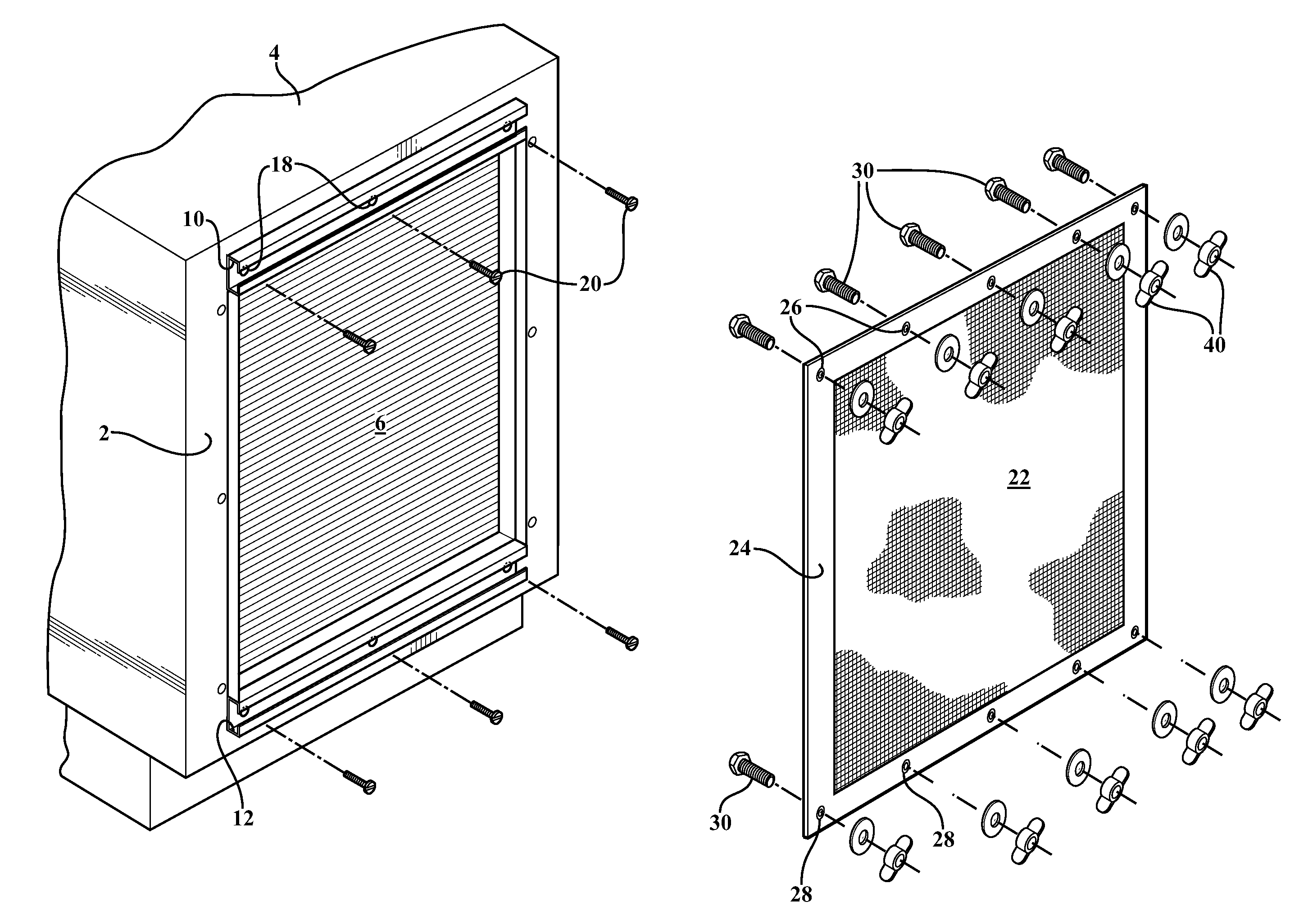
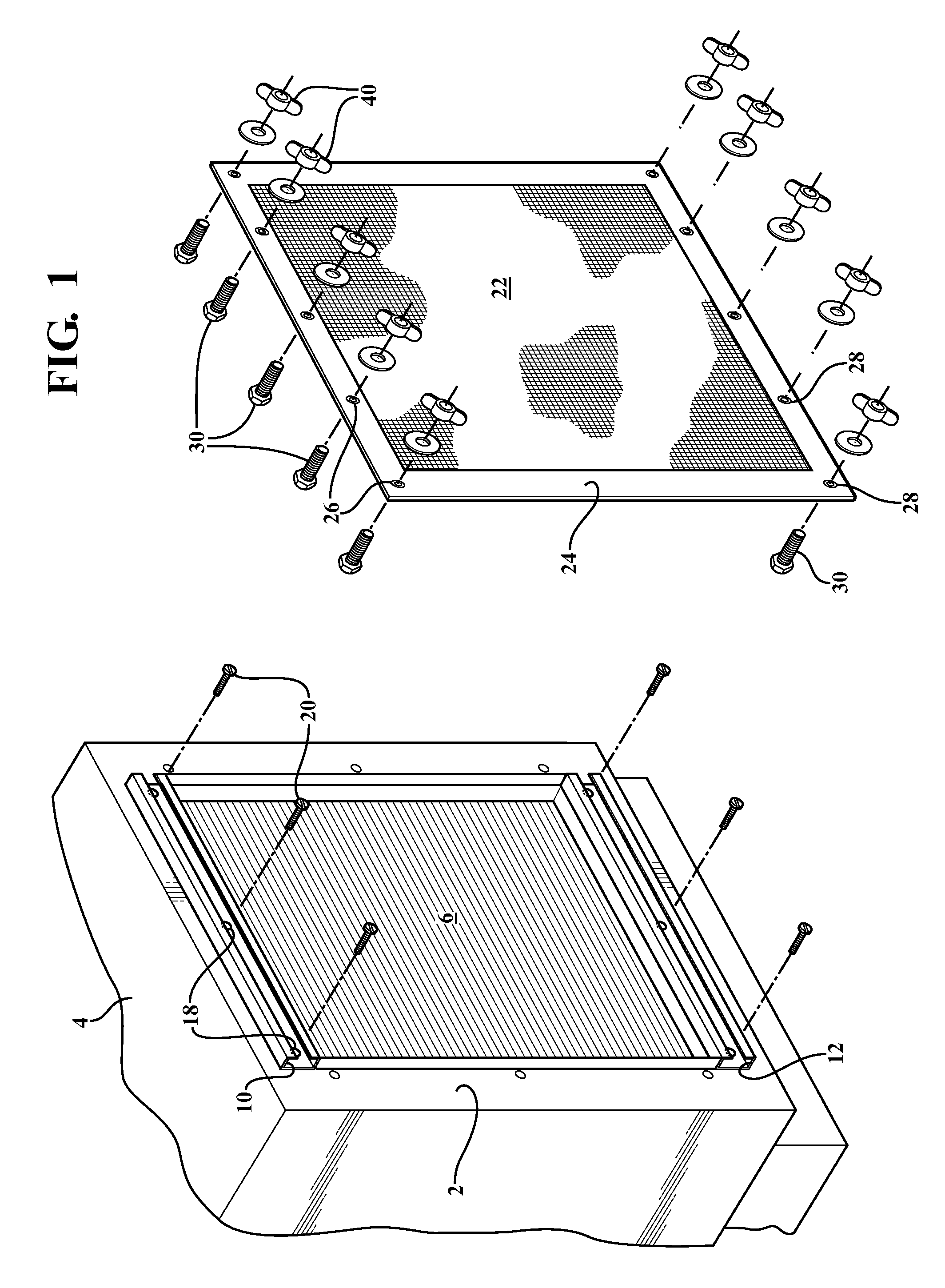
[0032]Referring to FIG. 1, an exploded view is generally depicted of the channel lock filter fastening system according to the present invention and exhibiting a single pair of upper and lower horizontal extending and fascia supporting rails, see at 10 and 12, which are secured at extending locations along a fascia surface 2 associated with an air intake structure 4 (such further understood to include any suitable type of air handling mechanical equipment not limited to air conditioner condenser units, cooling towers etc.). As further depicted in each of succeeding views FIGS. 3-6, each of the rails (see for example first upper horizontal extending rail 10) exhibits a three dimensional, and typically modified “U”, shape with a base surface (see at 14 in each of FIGS. 3-6).

[0033]A plurality of spaced apart apertures are defined by inner perimeter extending circular edges 18 (see again rail 10 in each of FIGS. 1 and 2). A plurality of screw fasteners 20 are provided and insert through...

second embodiment

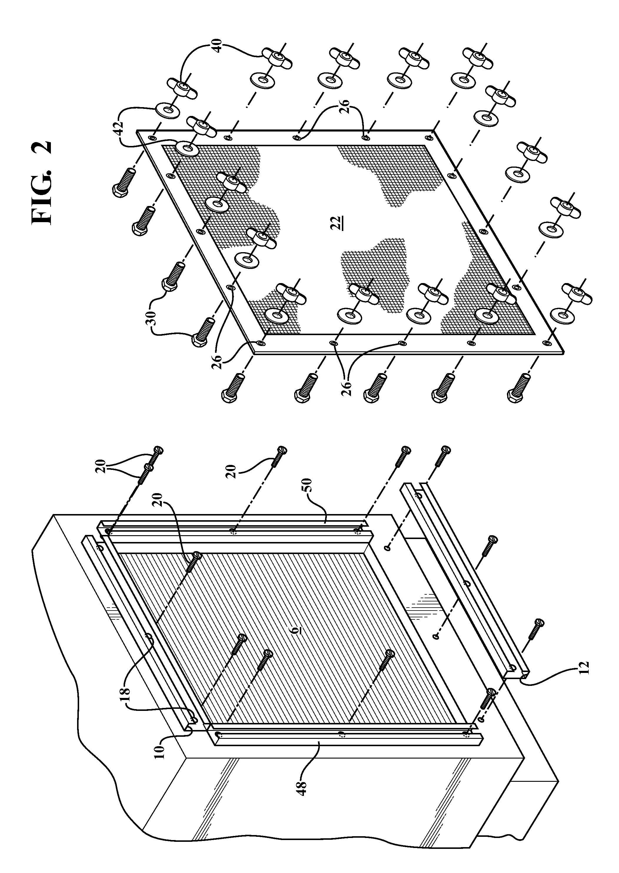
[0038]FIG. 2 is a view similar to FIG. 1 of a system which differs only to the extent that it adds a second vertical pair of intake face mounted rails 48 and 50 applied to opposite and vertically extending sides of the fascia 2 in such a fashion that the first (10 and 12) and second pairs (48 and 50) of rails collectively establish a generally rectangular shape (this including a square shape in the instance in which the sides of the intake opening and the lengths of all the rails are co-equal). Otherwise, the filter 22 is as previously disclosed in claim 1 with the corresponding modification to include additional grommets 26 likewise extending along the vertical side edges of the reinforced outer frame (also hem or skirt) with corresponding additional bolts 30, wing nuts 40 and washers 42 likewise being provided so as to progressively secure the filter 22 along each of four interconnecting edges and as opposed to only two upper and lower edges as is the case in the illustration of ...


PUM


Abstract

A fastening system for applying a covering material over an opening of a structure. At least one elongated rail is secured to a fascia of the structure in extending fashion proximate the opening and exhibits a shape with a forwardly projecting support surface within which is configured a narrowed slot. A plurality of fasteners each include a planar shaped base installable through an accessible end location of each of the rails so as to be traversable along an interior channel defined in the rail. A further rotatable portion of each fastener projects from the base through the outwardly facing slot to be rotated from a first position aligning with and seating over perimeter defined receiving apertures of the covering material to a second position in order to affix the material.

Description

CROSS REFERENCE TO RELATED APPLICATIONS[0001]The present application is a continuation-in-part of U.S. patent application Ser. No. 13 / 205,908, filed Aug. 9, 2011.FIELD OF THE INVENTION[0002]The present invention is directed to an assembly for securing a filter screen to a perimeter extending face surrounding a central opening of an air intake structure. More specifically, the present invention discloses a channel lock construction including any number (such as two to four) modified “U” cross sectional shaped rails which secure in generally parallel extending fashion to the edges of the intake opening. A plurality of bolt head fasteners are slidably installed within accessible open end channels of the “U” shaped rails, such that their threaded shafts project through a narrowed and lengthwise extending slot opening defined in each rail. The attachable filter screen exhibits a reinforced perimeter within which is configured a plurality of edge proximate and extending grommets through w...

Claims


Application Information

Patent Timeline
Patent Type & Authority Applications(United States)
IPC IPC(8): E04B1/38
CPCF24F13/082E06B9/52E06B9/01E06B9/24E06B2009/015E06B2009/527B01D46/42F24F13/28
Inventor SIMMONS, RANDY
Owner SIMMONS RANDY
Learn More