Eureka AIR delivers breakthrough ideas for toughest innovation challenges, trusted by R&D personnel around the world.

Radiation dosimeter with localization means and methods

a technology of localization and dosimeter, applied in the field of dosimeter, can solve the problems of affecting the performance of optical trackers, affecting the radiation effect of patients, and exposing healthy tissue to radiation

Inactive Publication Date: 2013-02-07
HALLIL ABDELBASSET
View PDF8 Cites 66 Cited by
  • Summary
  • Abstract
  • Description
  • Claims
  • Application Information

AI Technical Summary

Benefits of technology

The DosiLoc apparatus is a device that accurately measures radiation beams during treatment. It consists of a dosimeter and an optical marker that work together to provide a simultaneous measurement of the radiation dose and the patient's movement during treatment. The device can be attached to a support object and can be disposable or reusable. It can be used in a variety of settings and can be inserted in tubes or catheters for temporary or permanent use. The optical marker can be any shape or reflective material, and it can be used in combination with a magnetic sensor for absolute optical localization. The device allows for accurate and efficient treatment planning and monitoring.

Problems solved by technology

However, they suffer from the line of sight problem, in that any obstacle between sensor and source seriously degrades the tracker's performance.
Ambient light and infrared radiation also adversely affect optical tracker performance.
However, these systems only measure the position, but never measure the dose in conjunction with position.
However, this system has a flaw since movement alone would not be enough to determine the dose that was exposed to the patient.
The system does not measure the dose related to the position, thus causing patient's healthy tissue to be exposed to radiation.
Furthermore, the problem with optical trackers is that some system may block camera's visual site between optical marker leading to a loss of localization signal and can result into exposure to radiation of the healthy tissue cells.
In addition, the loss in localization sometimes does not allow the system to re-calibrate back to the region of interest and therefore resulting in an entire reboot of the system.
Also, another problem is the difficulty of position tracking in implanted areas as device cannot be implanted with all markers, and still be trackable by cameras.

Method used


Image

  • Radiation dosimeter with localization means and methods
  • Radiation dosimeter with localization means and methods
  • Radiation dosimeter with localization means and methods

Examples


Embodiment Construction

[0026]The following detailed description is provided to assist the reader in gaining a comprehensive understanding of the methods, apparatuses and / or systems described herein. Accordingly, various changes, modifications, and equivalents of the systems, apparatuses, and / or methods described herein will likely suggest themselves to those of ordinary skill in the art. Also, descriptions of well-known functions and constructions are omitted to increase clarity and conciseness.

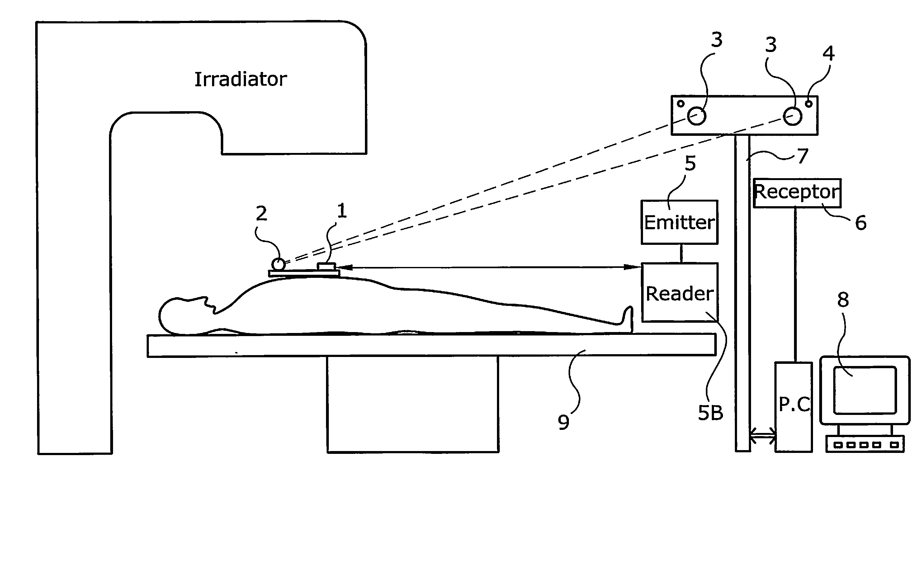
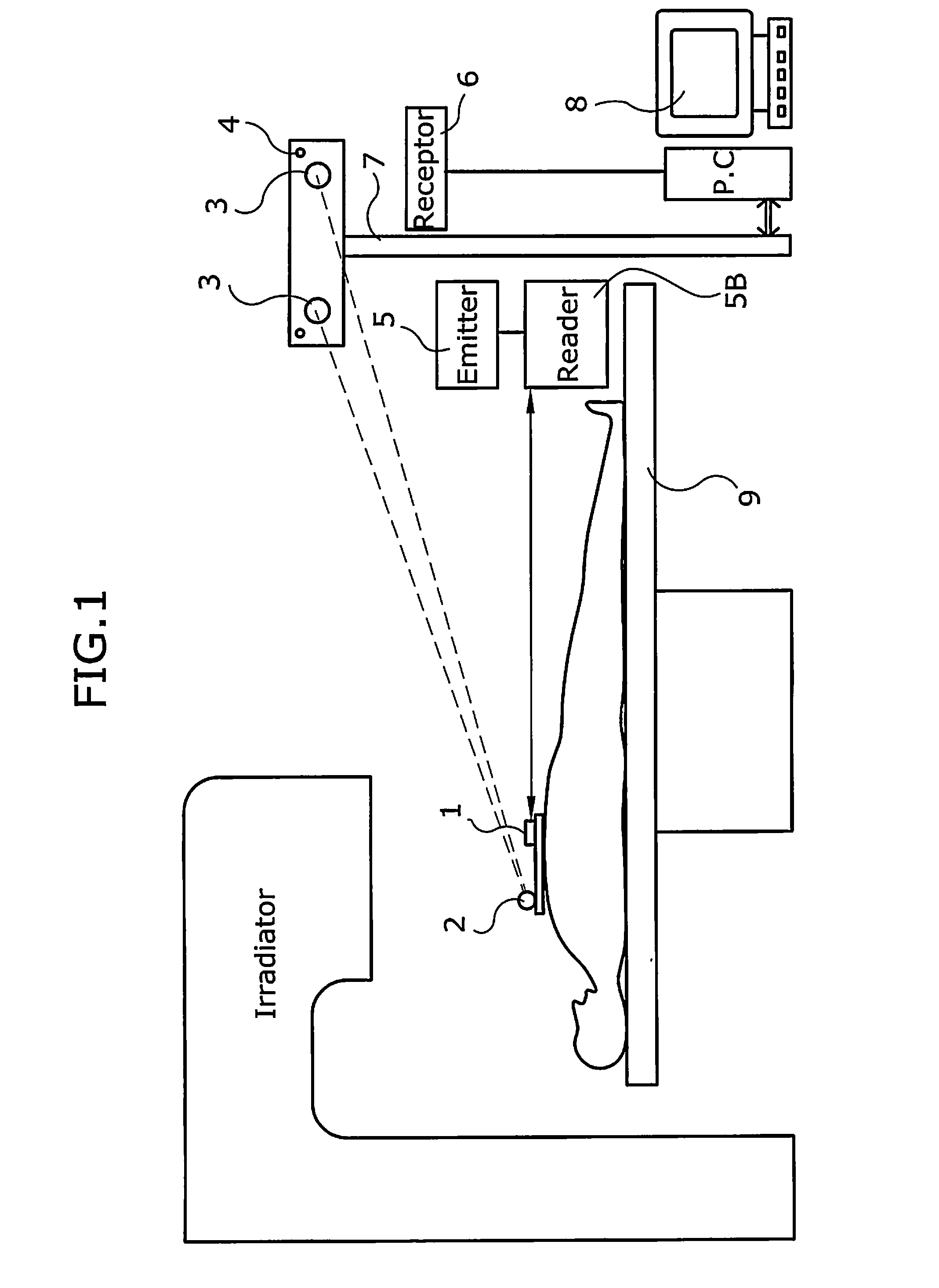
[0027]FIG. 1 illustrates how the DosiLoc is placed on the patient while having treatment performed. The DosiLoc contains a dosimeter 1 and an optical marker 2. The optical marker 2 is viewed by the camera 3. The camera 3 can be mounted on the wall, ceiling or may be placed on tripod stands 7. The camera support 7 can be static on fixtures determined by user in the treatment room (patient bed, ceiling, or etc.), while allowing line of sight with the optical markers 2. Alternatively, the camera support can be moved m...


PUM

PropertyMeasurementUnit
flexibleaaaaaaaaaa
thicknessaaaaaaaaaa
radio-opacityaaaaaaaaaa

Abstract

A apparatus for accurately measuring radiation beams during treatment which comprises a dosimeter which is used to measure the radiation; an optical marker which is used to determine the patient position; and said dosimeter and said optical marker are connected to one another used to provide and display simultaneously a radiation dose reading and a measurement of the patient's movements during treatment.

Description

CROSS REFERENCE TO RELATED APPLICATION[0001]N / AFIELD OF THE INVENTION[0002]The invention generally relates a dosimeter associated with an optical localization device to allow simultaneous dose and position measurement during radiotherapy procedures.BACKGROUND[0003]An optical tracking system typically consists of three subsystems. The three major components consist of an optical imaging system, a mechanical tracking platform and a tracking computer. The optical imaging system is responsible for converting the light from the target area into digital image that the tracking computer can process. Depending on the design of the optical tracking system, the optical imaging system can vary from as simple as a standard digital camera to as specialized as an astronomical telescope on the top of a mountain. The specification of the optical imaging system determines the upper-limit of the effective range of the tracking system.[0004]Most optical tracking devices currently used in virtual envir...

Claims


Application Information

Patent Timeline
Patent Type & Authority Applications(United States)
IPC IPC(8): G01T7/00G01B11/14G01N23/04
CPCG01B11/00A61N2005/1072A61N5/1071A61N2005/1059
Inventor HALLIL, ABDELBASSET
Owner HALLIL ABDELBASSET
Why Eureka
Eureka Blog
Learn More