
Wireless Open-Circuit In-Plane Strain and Displacement Sensor Requiring No Electrical Connections

a strain and displacement sensor, wireless open-circuit technology, applied in the direction of resistance/reactance/impedence, instruments, force measurement, etc., can solve the problems of increasing the cost of electrical devices, requiring manpower, and expensive use of solder

Active Publication Date: 2013-02-07
NASA
View PDF3 Cites 11 Cited by
  • Summary
  • Abstract
  • Description
  • Claims
  • Application Information

AI Technical Summary

Benefits of technology

The present invention provides a wireless strain sensor that does not require electrical connections. The sensor includes an electrical conductor and at least one electrode fixedly coupled to a substrate. The electrical conductor has a unique shape that creates an unconnected open-circuit with inductance and capacitance. When exposed to a time-varying magnetic field, the electrical conductor resonates to generate harmonic electric and magnetic field responses with associated frequencies, amplitudes, and bandwidths. The sensor also includes a motion guidance structure that maintains the electrode's free portion parallel to the electrical conductor. This invention allows for the accurate and non-invasive measurement of strain and displacement on a substrate without the need for electrical connections.

Problems solved by technology

Circuit repair or replacement causes downtime, requires manpower, and can be expensive.
The use of solder poses a number of problems.
Solder increases the cost of electrical devices and requires the use of venting and air filtration systems during fabrication due to the toxic nature of solder.
Further, the high heat required to melt solder can stress or damage circuit boards, and the presence of toxic solder also poses waste issues when old electrical circuits must be disposed of or recycled.
For all of these reasons, the typical electrical device has a number of inherent flaws.
Further, because solder and printed circuit boards are typically used to make closed circuits for the sensors discussed above, any reliability, hazardous material, and waste issues associated with solder directly affect them.

Method used


Image

  • Wireless Open-Circuit In-Plane Strain and Displacement Sensor Requiring No Electrical Connections
  • Wireless Open-Circuit In-Plane Strain and Displacement Sensor Requiring No Electrical Connections
  • Wireless Open-Circuit In-Plane Strain and Displacement Sensor Requiring No Electrical Connections

Examples


Embodiment Construction

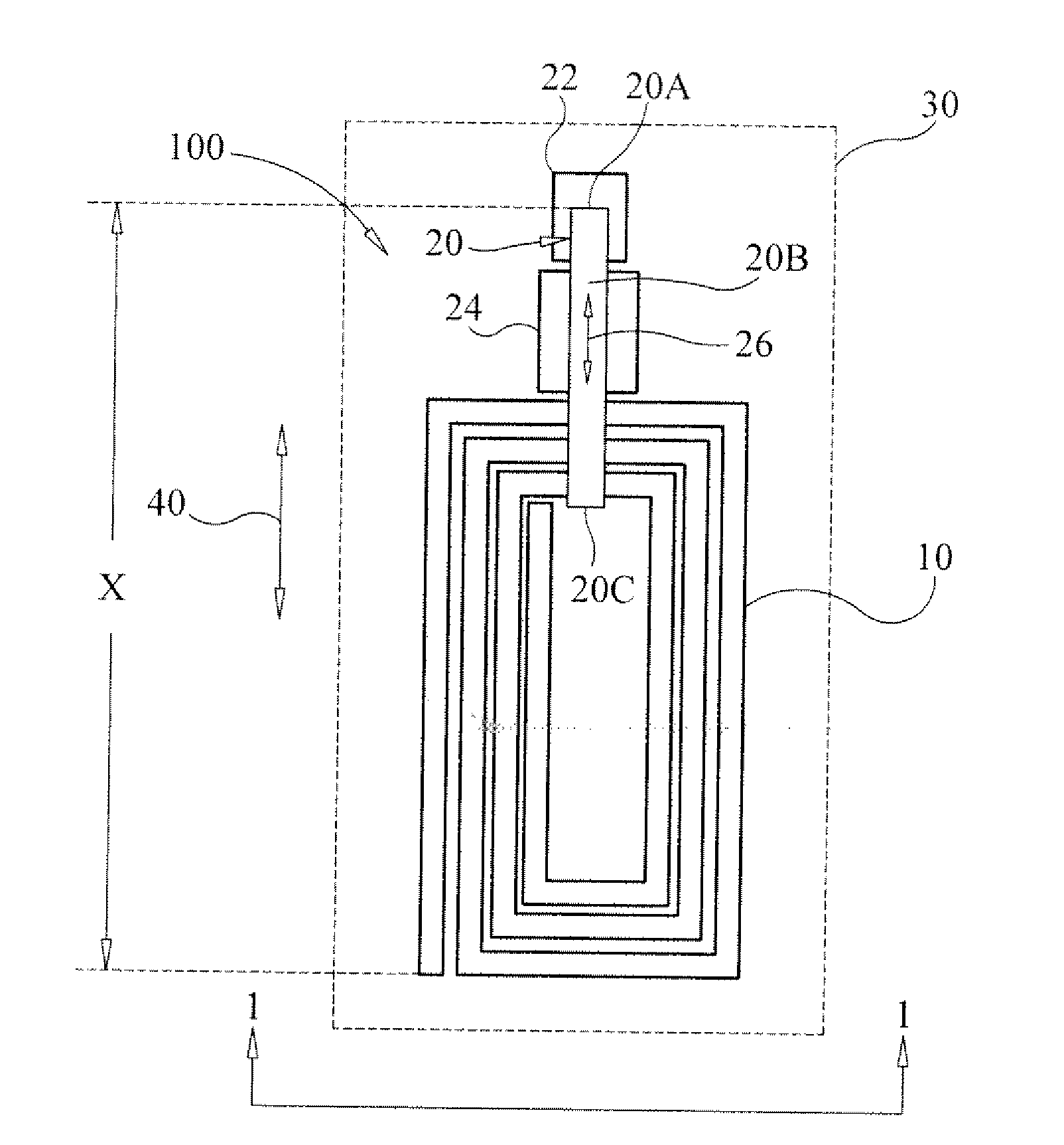
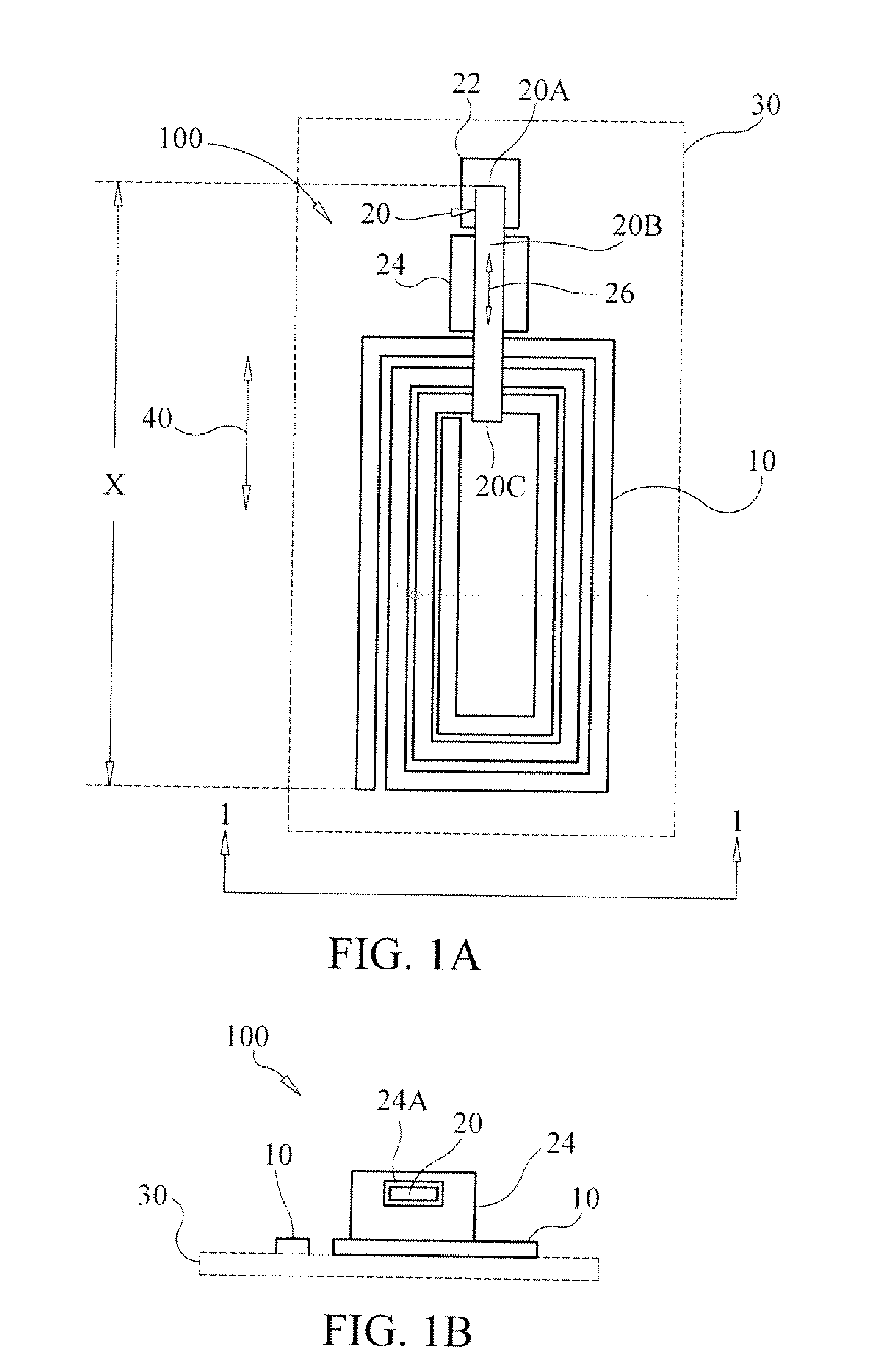
[0016]Referring now to the drawings and more particularly to FIGS. 1A and 1B, a wireless in-plane strain and displacement sensor in accordance with an embodiment of the present invention is shown and is referenced generally by numeral 100. The illustrated sensor 100 is presented as an exemplary embodiment as there will be many possible embodiments that can be constructed based on the basic principles of the present invention without departing from the scope thereof. In the illustrated embodiment, sensor 100 includes a pattern 10 of electrically conductive material and an electrically unconnected electrode 20 spaced apart from pattern 10.

[0017]Electrical conductor pattern 10 is any electrical conductor (e.g., wire, run, thin-film trace, etc.) that can be shaped to form an open-circuit pattern that can store an electric field and a magnetic field. Pattern 10 is a single-component open-circuit element with no electrical connections being made thereto. The term “open-circuit pattern” as...


PUM


Abstract

A wireless in-plane strain and displacement sensor includes an electrical conductor fixedly coupled to a substrate subject to strain conditions. The electrical conductor is shaped between its ends for storage of an electric field and a magnetic field, and remains electrically unconnected to define an unconnected open-circuit having inductance and capacitance. In the presence of a time-varying magnetic field, the electrical conductor so-shaped resonates to generate harmonic electric and magnetic field responses. The sensor also includes at least one electrically unconnected electrode having an end and a free portion extending from the end thereof. The end of each electrode is fixedly coupled to the substrate and the free portion thereof remains unencumbered and spaced apart from a portion of the electrical conductor so-shaped. More specifically, at least some of the free portion is disposed at a location lying within the magnetic field response generated by the electrical conductor. A motion guidance structure is slidingly engaged with each electrode's free portion in order to maintain each free portion parallel to the electrical conductor so-shaped.

Description

ORIGIN OF THE INVENTION[0001]The invention was made by an employee of the United States Government and may be manufactured and used by or for the Government of the United States of America for governmental purposes without the payment of any royalties thereon or therefore.BACKGROUND OF THE INVENTION[0002]1. Field of the Invention[0003]This invention relates to wireless electrical devices. More specifically, the invention is a wireless in-plane strain and displacement sensor requiring no electrical connections.[0004]2. Description of the Related Art[0005]Electrical devices typically utilize a plurality of circuit elements wired together to form a circuit. As is well understood in the art, such electrical devices function for a designed purpose when electric current flows through the circuit. If an unwanted break occurs in the circuit, electric current ceases to flow and the circuit must be repaired or replaced to restore device function. Circuit repair or replacement causes downtime,...

Claims


Application Information

Patent Timeline
Patent Type & Authority Applications(United States)
IPC IPC(8): G01R27/04
CPCG01L1/26G01L1/14
Inventor WOODARD, STANLEY E.
Owner NASA
Learn More