
System and method for controlling straddle-type vehicle

a technology of straddle-type vehicles and control systems, which is applied in the direction of process and machine control, cycle equipment, instruments, etc., can solve the problems of increasing the baking distance of the vehicle, the motorcycle's attitude may become unstable, and the vehicle cannot achieve the desired driving power performance, so as to improve the driving power performance and braking performance, and the effect of preventing the wheel from sliding

Active Publication Date: 2013-01-31
KAWASAKI MOTORS LTD
View PDF4 Cites 27 Cited by
  • Summary
  • Abstract
  • Description
  • Claims
  • Application Information

AI Technical Summary

Benefits of technology

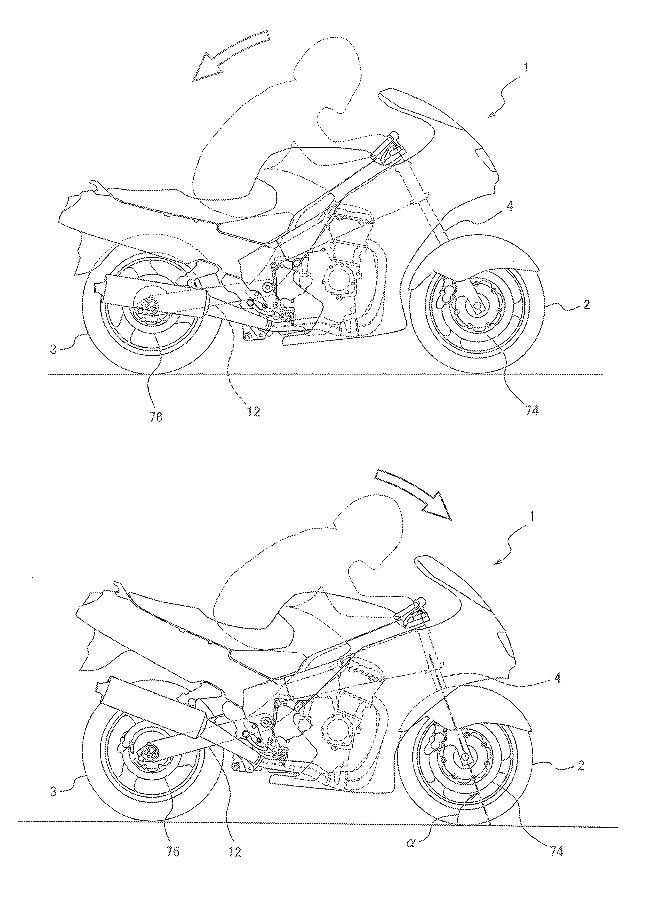
The present invention relates to a method for improving the driving performance and braking performance of a straddle-type vehicle by actively changing the ground load distribution between the front and rear wheels during acceleration or braking. This is achieved by utilizing the load shifting characteristic of the vehicle, while suppressing slippage of the wheels. By controlling the ground load distribution, the vehicle's power and braking performance can be enhanced without reducing the driving power or braking force applied to the wheel. This control method, known as theADC control, combines well with existing slip control methods such as TRC or ABS, reducing the degree of power or braking force reduction and minimizing the frequency of slip control. The load distribution control and slip control can be implemented separately, ensuring responsiveness of each control method. Overall, the invention provides a more effective and efficient way to control the vehicle's load distribution and enhance its performance.

Problems solved by technology

In that case, the attitude of the motorcycle may become unstable.
Therefore, there may be a chance that a desired driving power performance is not attained, or a baking distance of the vehicle increases.
The above stated suspension control can stabilize the attitude of the vehicle effectively, but cannot enhance the driving power performance and cannot reduce the braking distance.
Because of this, even if the suspension control is used in combination with the TRC control or the ABS control, the above stated problems associated with the TRC control and the ABS control cannot be resolved.

Method used


Image

  • System and method for controlling straddle-type vehicle
  • System and method for controlling straddle-type vehicle
  • System and method for controlling straddle-type vehicle

Examples


embodiment 1

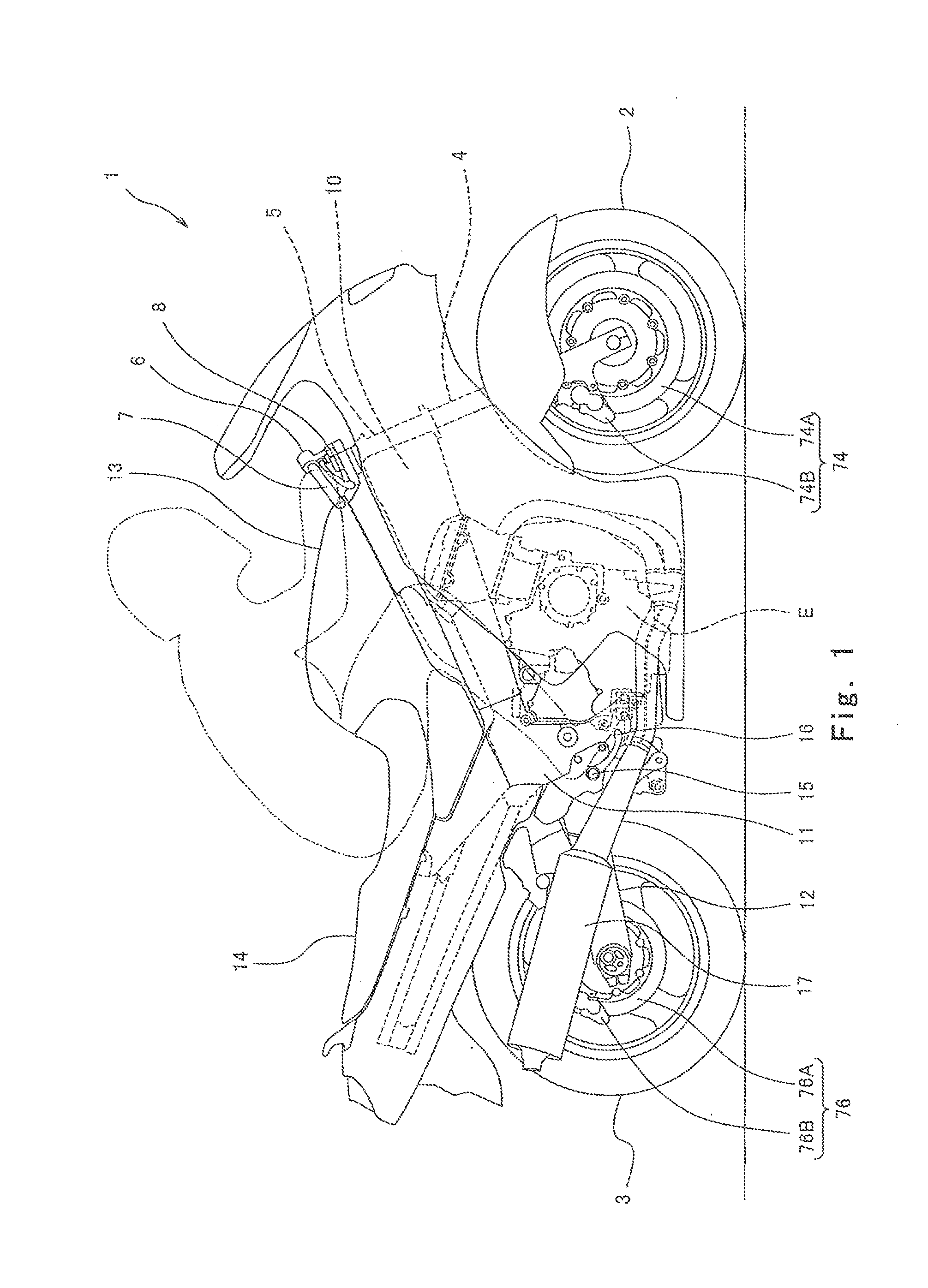
[0041]FIG. 1 is a right side view of a motorcycle 1 according to an embodiment of the present invention. Referring to FIG. 1, the motorcycle 1 includes a front wheel 2 which is a driven wheel and a rear wheel 3 which is a drive wheel. The front wheel 2 is rotatably mounted to lower end portions of a pair of right and left front forks 4 extending substantially vertically. The upper portions of the right and left front forks 4 are coupled together via a pair of upper and lower brackets (not shown), and rotatably supported by a head pipe 5 provided on a vehicle body. A bar-type steering handle 6 extending in a rightward and leftward direction is attached to the upper bracket. The driver grips and manipulates the steering handle 6 to actuate the front forks 4 and the front wheel 2 around the head pipe 5.

[0042]A throttle grip 7 which can be gripped by the driver's right hand is provided at a right end of the steering handle 6. The driver rotates the throttle grip 7 by twisting the driver...

embodiment 2

[0116]Next, Embodiment 2 will be described. In Embodiment 2, during braking of the motorcycle 1, the damping force of the front fork 4 is reduced as in the case of Embodiment 1, and then is increased at a time point when the front fork 4 has been contracted to a substantially shortest length, thereby maintaining a state in which the ground load of the front wheel 2 is increased. In other respects, Embodiment 2 is identical to Embodiment 1, and the same components as those in Embodiment 1 are identified by the same reference symbols and will not be described in repetition.

[0117]Referring to FIG. 13 showing the second ADC control in step SA11 in the flow of FIG. 11, initially, in step SB1, a damping force reduction time (period) during which the damping force of the front fork 4 is reduced is set based on the driving state of the motorcycle 1. Then, in step SB2, a timer built into the suspension ECU 90 starts counting. In step SB3, the opening degree of the control valve of the valve ...

embodiment 3

[0122]Next, Embodiment 3 will be described. In Embodiment 3, during acceleration or braking of the motorcycle 1, the ADC control is performed in such a manner that the damping force corresponding to an extension of the cushion unit 18 or the front fork 4, and the damping force corresponding to a contraction of the cushion unit 18 or the front fork 4, are changed individually. In other respects, Embodiment 3 is identical to Embodiment 1, and the same components as those in Embodiment 1 are identified by the same reference symbols and will not be described.

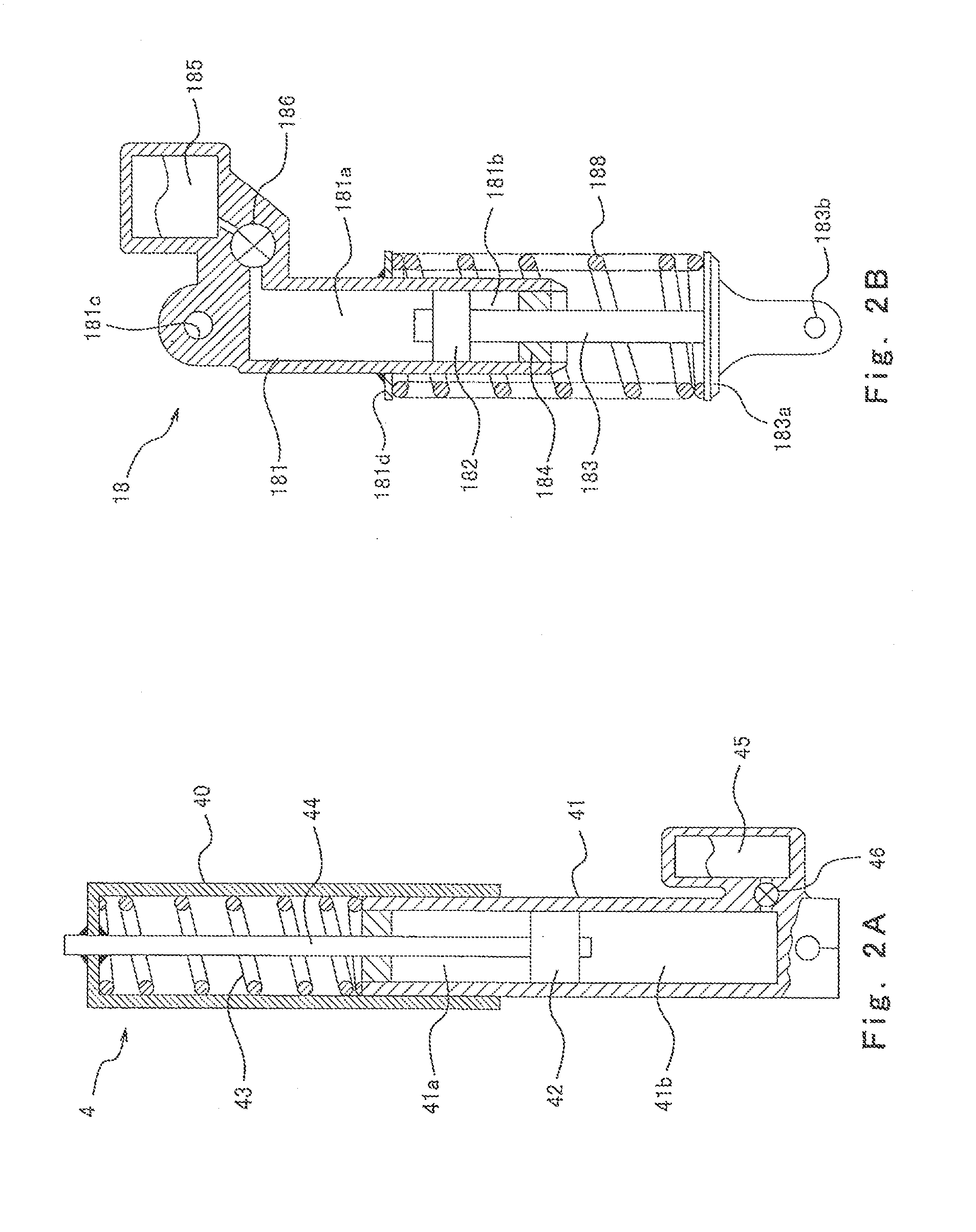
[0123]In Embodiment 3, the damping force corresponding to an extension and the damping force corresponding to a contraction of at least either the cushion unit 18 or the front fork 4 are changed individually. The configuration of such a buffer device is known and will not be shown. For example, the valve unit 46 of the front fork 4 of FIG. 2A is provided with a control valve capable of adjusting its opening degree to restrict only t...


PUM


Abstract

A control system in a straddle-type vehicle is provided. The control system includes front and rear wheels, comprises a load distribution changing section which changes a ground load distribution between the front and rear wheels during driving of the vehicle; a slip suppressing condition determiner section which determines whether or not a suppressing condition used to suppress a slip of one of the front and rear wheels is met, during driving of the vehicle; and a load distribution control section which controls the load distribution changing section to make the ground load of the one of the front and rear wheels greater when the slip suppressing condition determiner section determines that the suppressing condition is met, than when the slip suppressing condition determiner section determines that the suppressing condition is not met.

Description

BACKGROUND OF THE INVENTION [0001]1. Field of the Invention[0002]The present invention generally relates to control for straddle-type vehicles. More particularly, the present invention relates to a control technique for preventing a wheel slip from increasing excessively, for example, a wheel spin during acceleration or a wheel lock during braking.[0003]2. Description of the Related Art[0004]Conventionally, in straddle-type vehicles represented by motorcycles, which are lighter in weight than four-wheel vehicles, or the like, a ground load of a wheel (vertical load applied by the wheel), i.e., a pressing force applied by the wheel on a ground surface, is smaller, but its driving power is relatively greater. Therefore, a wheel spin, to be precise, a spin of a drive wheel, tends to occur in the straddle-type vehicle during acceleration. If a driver applies a brake strongly during braking, a wheel may be locked. In that case, the attitude of the motorcycle may become unstable.[0005]As ...

Claims


Application Information

Patent Timeline
Patent Type & Authority Applications(United States)
IPC IPC(8): B60G17/016
CPCB60T8/1706B60T13/662B60T8/3225B60T8/1766B60G17/08B60G2300/12B62K2025/044B60K28/165B60W10/06B60W10/188B60W10/22B60W30/18172B60W2300/36B60W2520/26B60T8/18
Inventor MATSUDA, YOSHIMOTO
Owner KAWASAKI MOTORS LTD
Learn More