
RF communications device including an optical link and related devices and methods

a communication device and optical link technology, applied in the field of radio frequency (rf) communication, can solve the problems of large attenuation effects of transmission signals over coaxial cables, difficulty in signal addressing, and large weight of components, and achieve efficient operation of rf signals

Active Publication Date: 2013-01-31
HARRIS CORP
View PDF1 Cites 14 Cited by
  • Summary
  • Abstract
  • Description
  • Claims
  • Application Information

AI Technical Summary

Benefits of technology

The present invention provides a communications device that operates efficiently on RF signals in the EHF band. The device includes a transmitter device that generates an optical carrier signal and modulates it with an input signal. A receiver device filters the modulated optical carrier signal to extract a desired sideband. The device also includes an optical-to-electrical converter that generates an output signal based on the selected sideband. The resulting signal has reduced degradation, making it easier to transmit and receive RF signals.

Problems solved by technology

For example, transmission of the signals over coaxial cable may incur large attenuation effects.
Moreover, in applications where RF devices are used, the size, weight, and power (SWaP) of the components may increase to undesirable levels.
Moreover, downstream receiver processing, such as downconverting, and signal addressing may be difficult.
Nevertheless, optical applications such as this may be subject to certain drawbacks.
For example, the systems may be subject to chromatic dispersion-induced signal fading.
In particular, optical heterodyne approaches may be limited by phase noise of laser sources.

Method used


Image

  • RF communications device including an optical link and related devices and methods
  • RF communications device including an optical link and related devices and methods
  • RF communications device including an optical link and related devices and methods

Examples


Embodiment Construction

[0021]The present invention will now be described more fully hereinafter with reference to the accompanying drawings, in which preferred embodiments of the invention are shown. This invention may, however, be embodied in many different forms and should not be construed as limited to the embodiments set forth herein. Rather, these embodiments are provided so that this disclosure will be thorough and complete, and will fully convey the scope of the invention to those skilled in the art. Like numbers refer to like elements throughout.

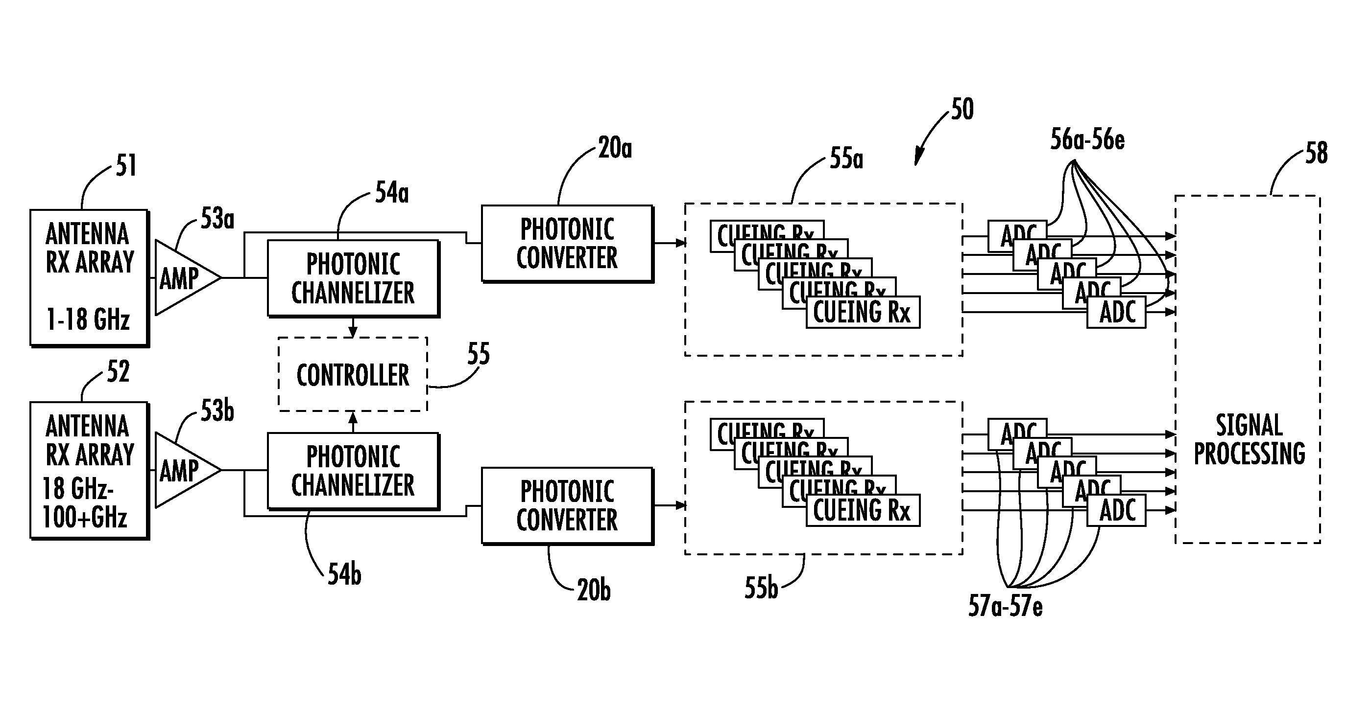
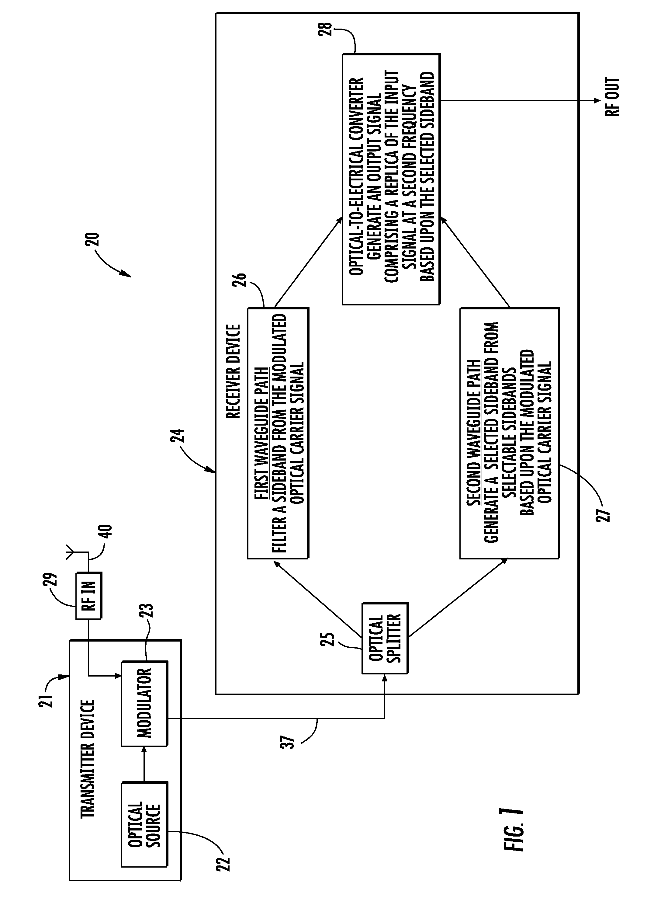
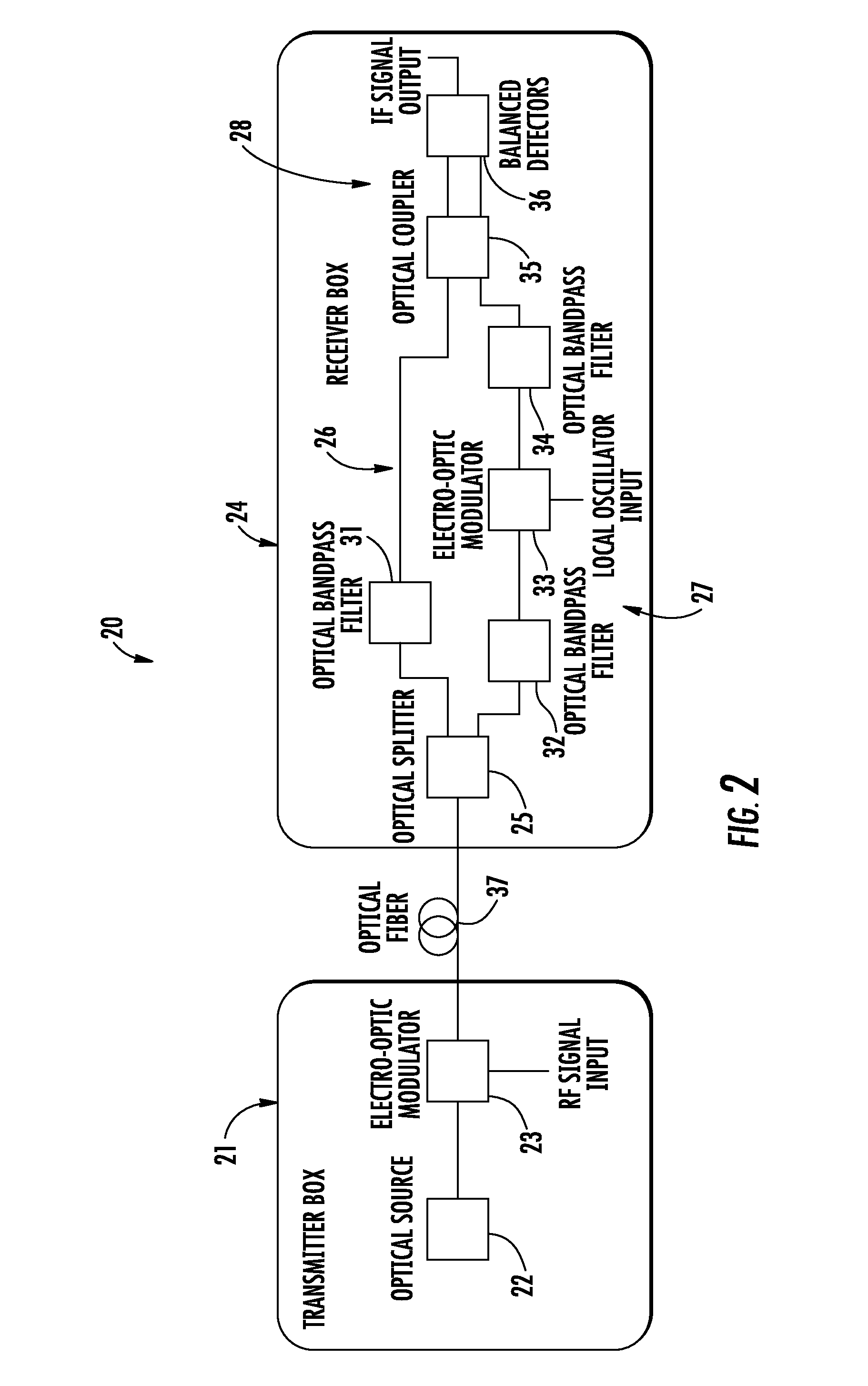
[0022]Referring initially to FIG. 1, a communications device 20 according to the present invention is now described. For example, the communications device 20 may operate as an optical link. The communications device 20 includes a transmitter device 21 including an optical source 22 configured to generate an optical carrier signal, and a modulator 23, for example, a Mach-Zehnder modulator, coupled to the optical source and configured to modulate the optica...


PUM


Abstract

A communications device includes a transmitter device including an optical source configured to generate an optical carrier signal, and a modulator coupled to the optical source and configured to modulate the optical carrier signal with an input signal having a first frequency, an optical waveguide coupled to the transmitter device, and a receiver device coupled to the optical waveguide. The receiver device includes an optical splitter, a first waveguide path coupled to the optical splitter and configured to filter a sideband from the modulated optical carrier signal, a second waveguide path coupled to the optical splitter and configured to generate a selected sideband from selectable sidebands based upon the modulated optical carrier signal, and an optical-to-electrical converter coupled to the first and second waveguide paths and configured to generate an output signal including a replica of the input signal at a second frequency based upon the selected sideband.

Description

FIELD OF THE INVENTION[0001]The present invention relates to the field of communications, and, more particularly, to radio frequency (RF) communications and related methods.BACKGROUND OF THE INVENTION[0002]A typical wireless communication system comprises a plurality of wireless communications devices exchanging data with each other. In some wireless communication systems, for example, infrastructure networks, the system may further comprise a wireless base station for managing communications between the wireless communications devices. In other words, each intra-system communication would be exchanged via the wireless base station. In other wireless communication systems, for example, mesh networks and ad hoc wireless networks, the wireless base station may be omitted, i.e. the wireless communications devices may communicate directly with each other.[0003]A typical Extremely High Frequency (EHF), i.e. 30 to 300 GHz, communication system operating at this band may have some drawback...

Claims


Application Information

Patent Timeline
IPC IPC(8): H04B10/16H04B10/24
CPCH04B2210/006H04B10/25758
Inventor DESALVO, RICHARDMIDDLETON, CHARLESSCHEUTER, PETER S.DEIBNER, GUS W.
Owner HARRIS CORP
Learn More