
Multiple path discrete digital receiver

a digital receiver and multi-path technology, applied in the field of wireless communication systems, can solve the problems of difficult to redesign the analog portion, and achieve the effect of improving the quality of the analog portion

Active Publication Date: 2013-01-31
AVAGO TECH INT SALES PTE LTD
View PDF10 Cites 8 Cited by
  • Summary
  • Abstract
  • Description
  • Claims
  • Application Information

AI Technical Summary

Benefits of technology

The patent text describes a wireless communication device that includes a built-in radio transceiver or is coupled to an associated radio transceiver for wireless communications. The device includes a plurality of integrated circuits and discrete components necessary to achieve the strict performance requirements of wireless communication standards. The technical effect of the patent is to provide a more efficient and cost-effective way to manufacture wireless transceivers for wireless communication devices.

Problems solved by technology

Redesigning the analog portions, however, is not a straightforward task since most analog circuitry (e.g., inductors, capacitors, etc.) does not “shrink” with the IC process.

Method used


Image

  • Multiple path discrete digital receiver
  • Multiple path discrete digital receiver
  • Multiple path discrete digital receiver

Examples


Embodiment Construction

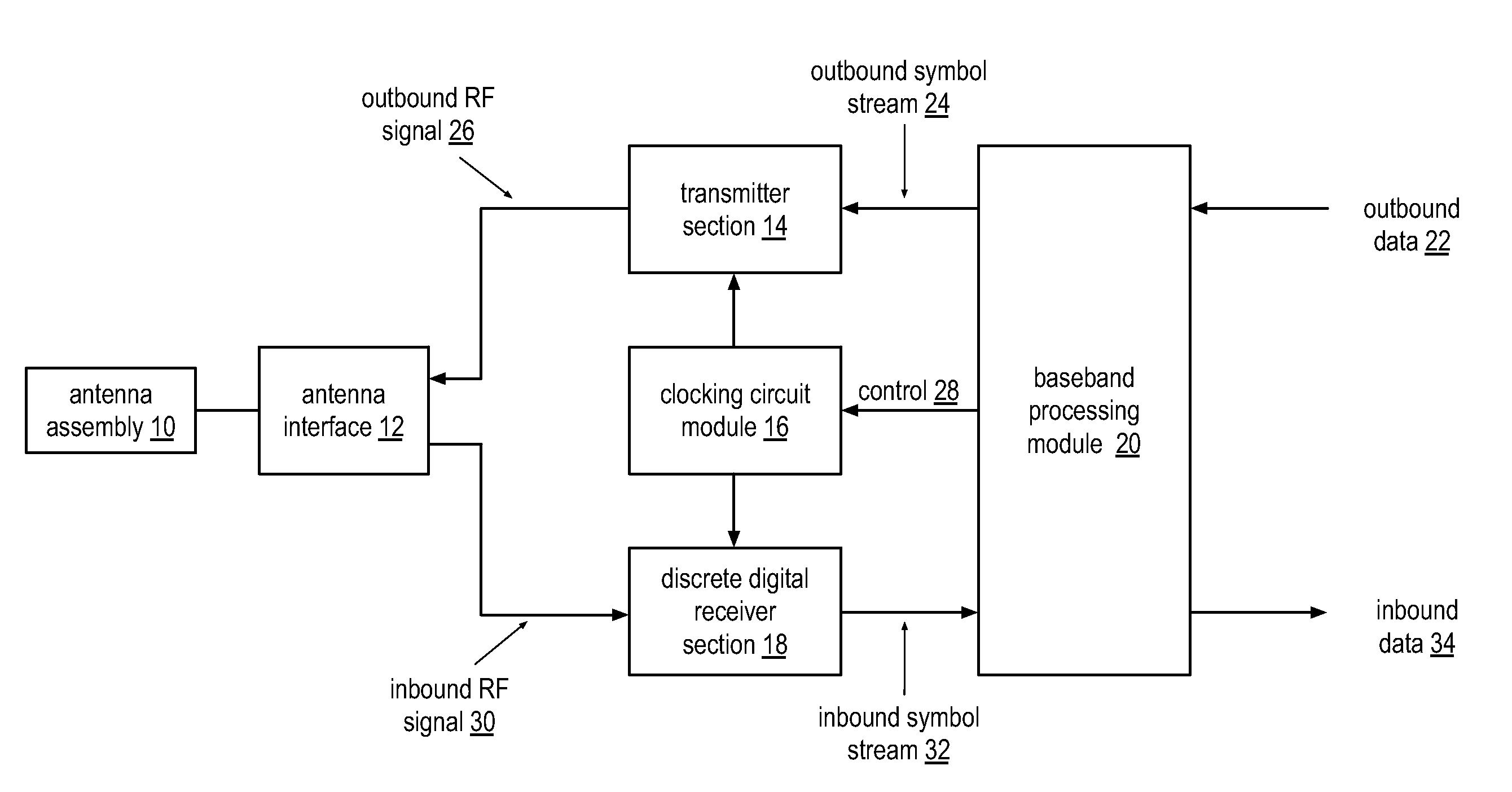
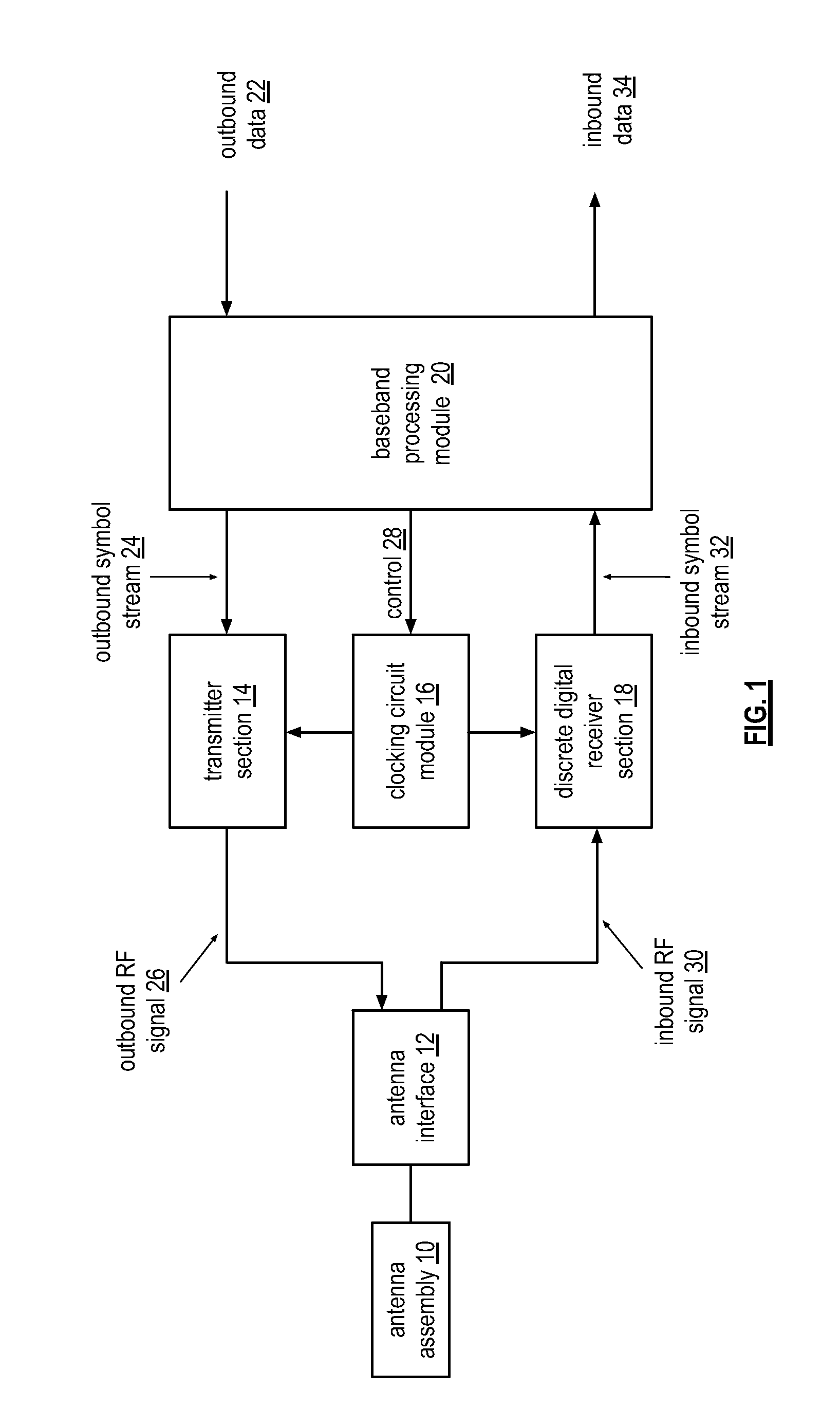
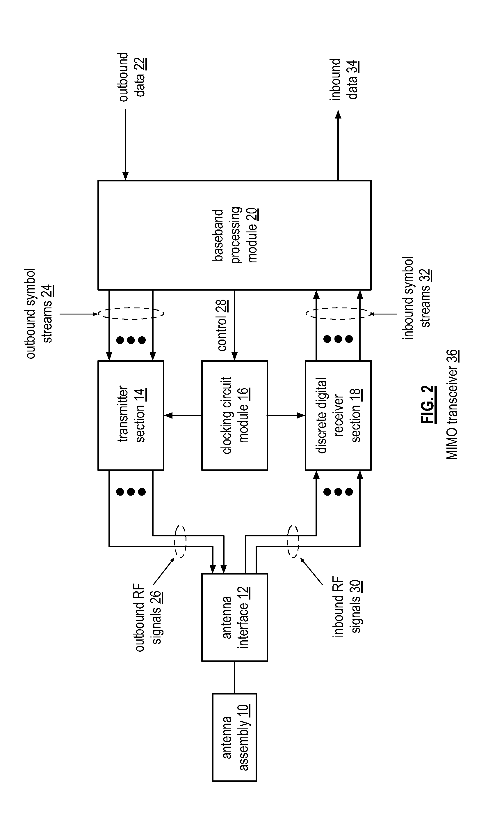
[0143]FIG. 1 is a schematic block diagram of an embodiment of a wireless transceiver that includes an antenna assembly 10, an antenna interface 12, a transmitter section 14, a clocking circuit module 16, a discrete digital receiver section 18, and a baseband processing module 20. The antenna assembly 10 may include one or more antennas, one or more antenna arrays, a diversity antenna structure, one or more separate transmit antennas, one or more separate receive antennas, and / or a combination thereof. The antenna interface 12 includes one or more antenna tuning units, one or more transmission lines, one or more impedance matching circuits, one or more transformer baluns, one or more transmit—receive switches, one or more transmit—receive isolation modules, etc. The wireless transceiver may further include a power management module (not shown).

[0144]The wireless transceiver may be included within a portable computing communication device, which may be any device that can be carried b...


PUM


Abstract

A receiver includes a bandpass filter module, a sample and hold module, first and second discrete time filter modules, and first and second conversion modules. The bandpass filter module is operable to filter an inbound wireless signal. The sample and hold module is operable to sample and hold the filtered inbound wireless signal to produce a frequency domain sample pulse train. The first discrete time filter module is operable to filter the frequency domain sample pulse train to produce a first filtered sample pulse. The second discrete time filter module is operable to filter the frequency domain sample pulse train to produce a second filtered sample pulse. The first conversion module is operable to convert the first filtered sample pulse into a first inbound baseband signal. The second conversion module is operable to convert the second filtered sample pulse into a second inbound baseband signal.

Description

CROSS REFERENCE TO RELATED PATENTS[0001]This patent application is claiming priority under 35 USC §120 as a continuing patent application of co-pending patent application entitled DISCRETE DIGITAL RECEIVER, having a filing date of Sep. 22, 2011, and a Ser. No. 13 / 240,639 (Attorney Docket Number BP23555), which is incorporated herein by reference and which claims priority under 35 USC §119(e) to a provisionally filed patent application entitled DISCRETE DIGITAL RF TRANSCEIVER, having a provisional filing date of Jul. 31, 2011, and a provisional Ser. No. 61 / 513,627 (Attorney Docket Number BP23021), which is incorporated by reference herein.STATEMENT REGARDING FEDERALLY SPONSORED RESEARCH OR DEVELOPMENT[0002]Not ApplicableINCORPORATION-BY-REFERENCE OF MATERIAL SUBMITTED ON A COMPACT DISC[0003]Not ApplicableBACKGROUND OF THE INVENTION[0004]1. Technical Field of the Invention[0005]This invention relates generally to wireless communication systems and more particularly to wireless communi...

Claims


Application Information

Patent Timeline
IPC IPC(8): H04B1/10
CPCH04B1/001H03H2015/007H03H19/00H04B1/0028H03H7/38H04L25/03
Inventor DARABI, HOOMAN
Owner AVAGO TECH INT SALES PTE LTD
Learn More