
Lighting and/or signaling device for a motor vehicle including a surface light source

a signaling device and motor vehicle technology, applied in the field of optical devices, can solve the problems of loss of the “signature” of lighting and/or signaling devices at night, large disparity between the useful lit-up surface area and the full outer surface area of the lamp, etc., to achieve the effect of increasing the cost, improving the appearance of lighting and/or signaling devices, and allowing greater freedom of form

Inactive Publication Date: 2013-01-31
VALEO VISION SA
View PDF9 Cites 9 Cited by
  • Summary
  • Abstract
  • Description
  • Claims
  • Application Information

AI Technical Summary

Benefits of technology

The aim of this invention is to improve the appearance of lighting and signaling devices by giving them a homogeneous luminous appearance in any direction of observation, without adding complexity or cost. This is achieved by using a main light source that produces most of the light for the device, and an auxiliary light source that produces a specific lit effect. The two sources are preferably on simultaneously and of the same color. The advantage is improved legibility of the device's functions for other drivers.

Problems solved by technology

However, although this “signature” is clear during the day when the lamp or headlamp is off, the same is not true at night when they are on.
This is particularly the case with lamps having a large outer surface area, of the “wrap-around” lamp type, i.e. lamps which extend not only over the front or rear face of the vehicle but also over the side thereof at the connecting part of a wing with this front or rear face: in this specific case, there is often great disparity between the useful lit-up surface area and the full outer surface area of the lamp.
There is therefore a tendency at night to lose the “signature” of lighting and / or signaling devices.
Nevertheless, such a solution poses a certain number of problems, in particular problems of complexity of implementation.
These constraints make the signaling device difficult to implement and expensive.

Method used


Image

  • Lighting and/or signaling device for a motor vehicle including a surface light source
  • Lighting and/or signaling device for a motor vehicle including a surface light source
  • Lighting and/or signaling device for a motor vehicle including a surface light source

Examples


first embodiment

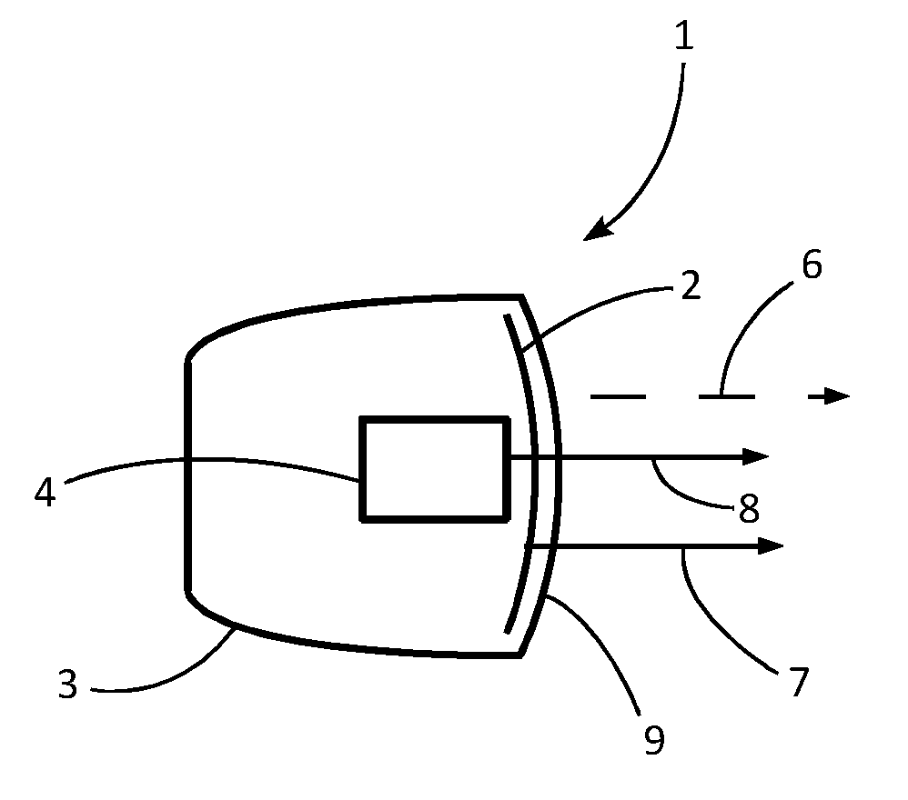
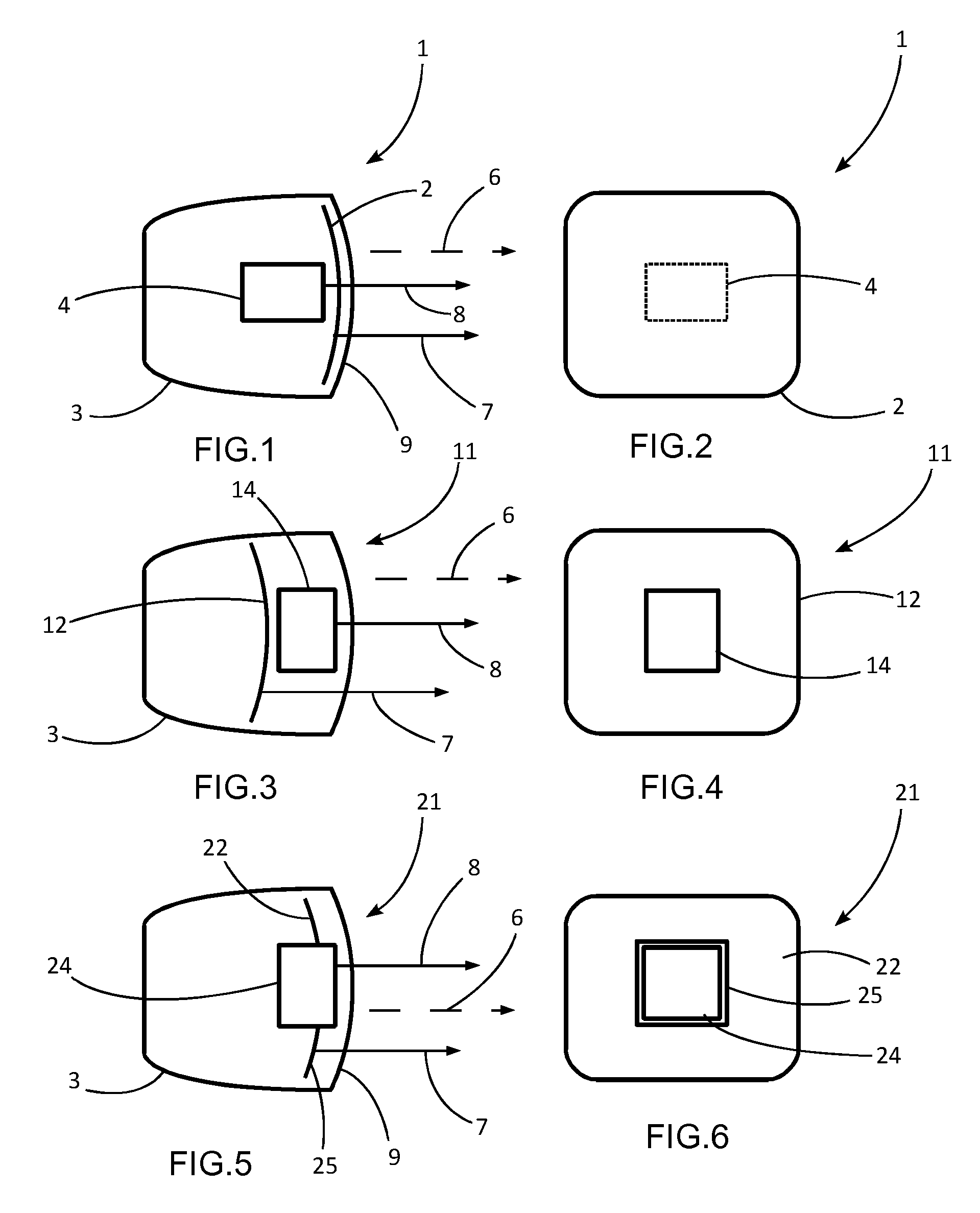
[0046]In a first embodiment, described hereafter with reference to FIGS. 1 and 2, the optical device is a lighting and / or signaling device 1 comprises a housing 3 closed by a cover lens 9. The lighting and / or signaling device 1 comprises at least one main light source 4 and at least one auxiliary light source 2. The main light source 4 emits light rays 8 and produces the greater part of the light for providing a lighting and / or signaling function. Preferably, the main light source 4 produces the entire light for providing the lighting and / or signaling function. Preferably, the auxiliary light source 2 emits light rays 7 and produces a particular lit effect of the lighting and / or signaling device 1. In particular, the auxiliary light source 2 can provide for making the appearance of the lighting and / or signaling device 1 homogeneous when the latter is on.

[0047]In this first embodiment, the auxiliary light source 2 is placed between the cover lens 9 and the main light source 4. Thus, ...

second embodiment

[0048]In a second embodiment, described hereafter with reference to FIGS. 3 and 4, the lighting and / or signaling device 11 differs from that described previously in that the main light source 14 is inserted between the cover lens 9 and the auxiliary light source 12. Thus, the light rays 8 emitted by the main light source 14 reach the cover lens 9 directly in order to exit the lighting and / or signaling device 11. However, only the light rays 7 emitted by the auxiliary light source 12 and located around the main light source 14 reach the cover lens 9. A part of the light rays 7 emitted by the auxiliary light source 12 happens to be stopped by the main light source 14. Since the auxiliary light source 12 is located behind the main light source 14, the latter is represented in solid line in FIG. 4.

third embodiment

[0049]In a third embodiment, described hereafter with reference to FIGS. 5 and 6, the lighting and / or signaling device 21 differs from those described with reference to FIGS. 1 to 4 in that main light source 24 is located at least substantially at the same level as the auxiliary light source 22. In particular, the main light source 24 can be located in the same plane as the auxiliary light source 22. For example, a cutout 25 is made in the auxiliary light source 22. Thus, the main light source 24 can be arranged in the cutout 25. The light rays 8 emitted by the main light source 24, like the light rays 7 emitted by the auxiliary light source 22, reach the cover lens 9 directly in order to exit the lighting and / or signaling device 21. The auxiliary light source 22 surrounds the main light source 24. The main light source 24 provides the photometry of the lighting and / or signaling function and the auxiliary light source 22 produces the signature of the lighting and / or signaling device...


PUM


Abstract

An optical device for a motor vehicle, in particular a lighting and / or signaling device for a motor vehicle, comprising a main light source and an auxiliary light source, wherein the auxiliary light source comprises a surface light source.

Description

CROSS-REFERENCE TO RELATED APPLICATIONS[0001]This application claims priority to PCT Application PCT / EP2011 / 052394 filed Feb. 18, 2011, and also to French Application No. 1051610 filed Mar. 5, 2010, which applications are incorporated herein by reference and made a part hereof.BACKGROUND OF THE INVENTION[0002]1. Field of the Invention[0003]The present invention relates to an optical device, in particular for a motor vehicle, such as a lighting and / or signaling device having in particular a photometric function that is useful when the vehicle is moving on the road, allowing the vehicle to be seen by other vehicles or allowing the driver of the vehicle to see outside.[0004]2. Description of the Related Art[0005]In the signaling field, just as in the lighting field, there are a large number of regulations which do not leave much room for modifying the appearance of lamps in the on state, since the photometry of the light beams is enforced to a very large extent. However, style and aest...

Claims


Application Information

Patent Timeline
Patent Type & Authority Applications(United States)
IPC IPC(8): F21S8/10F21V5/04F21Y113/20
CPCB60Q1/0052B60Q1/0058F21S48/1195F21Y2113/02F21Y2105/00F21Y2105/008F21S48/20F21Y2113/20F21Y2115/15F21S41/155F21S41/18F21S41/50F21S43/145F21S43/50
Inventor DUBOSC, CHRISTOPHEALBOU, PIERREGODBILLON, VINCENT
Owner VALEO VISION SA
Learn More