
Power supply for downhole instruments

Inactive Publication Date: 2013-01-31
FASTCAP SYST
View PDF1 Cites 89 Cited by
  • Summary
  • Abstract
  • Description
  • Claims
  • Application Information

AI Technical Summary

Benefits of technology

The patent text describes a power supply for a downhole tool that operates at high temperatures (80 to210 degreesCelsius). The power supply includes an energy source, a control circuit, and a rechargeable energy storage that can operate within this temperature range. The energy source can be a battery, an external power source, or a generator that translates energy from the downhole tool into electrical energy. The control circuit receives and stores the electrical energy from the energy source. The technical effect of this patent is the provision of a reliable power supply for downhole tools, which can operate at high temperatures and can be recharged when energy is spent. This ensures consistent performance of the downhole tool and minimizes the risk of malfunctions or damage due to lack of power.

Problems solved by technology

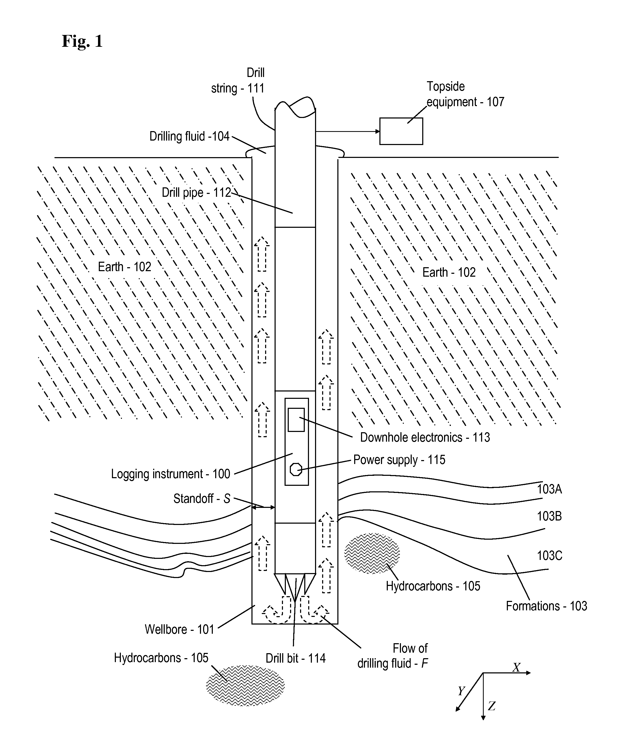
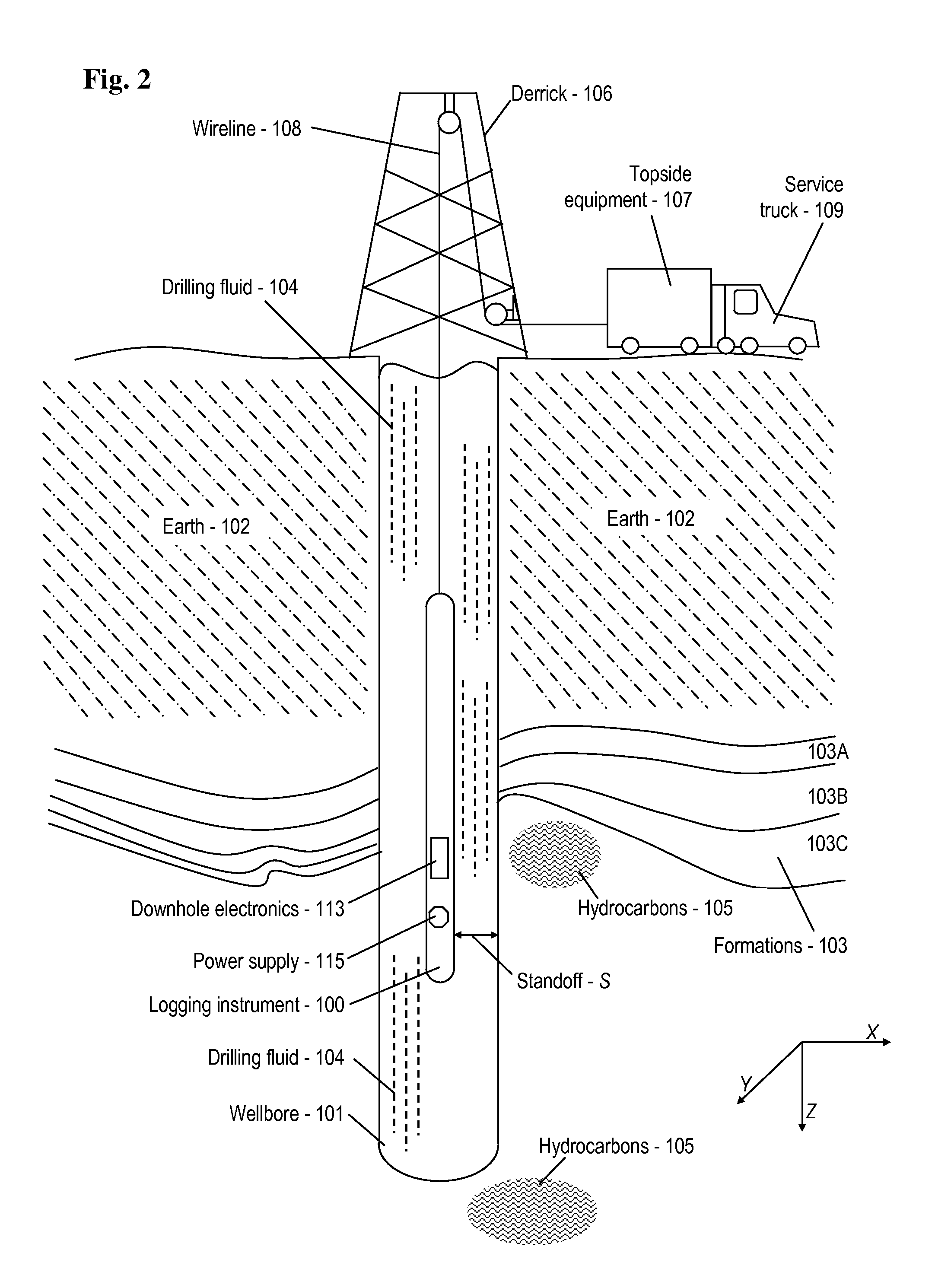
While drilling of the wellbore permits individuals and companies to evaluate sub-surface materials and to extract desired hydrocarbons, many problems are encountered.
Generally, present day instrumentation is not built to operate in such an environment, and will fail well before reaching ambient temperatures within this range.
The growing complexity of downhole instrumentation further complicates this problem.
Unfortunately, many of the known solutions have substantial drawbacks.
For example, various types of batteries suffer catastrophic failure at elevated temperature, and can thus destroy instrumentation.
Additionally, such batteries often are not rechargeable, as well as quite expensive.

Method used


Image

  • Power supply for downhole instruments
  • Power supply for downhole instruments
  • Power supply for downhole instruments

Examples


first embodiment

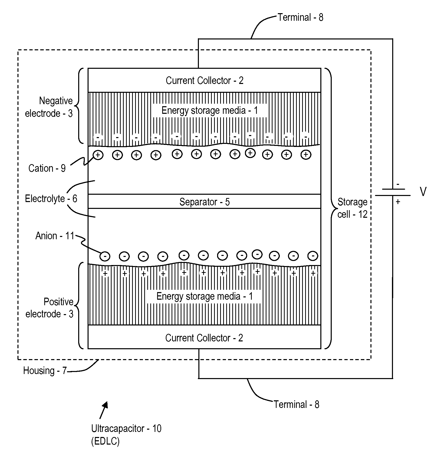
[0096]With regard to anions 11 suited for use in an ionic liquid that provides the electrolyte 6, various organic anions 11 may be used. Exemplary anions 11 and structures thereof are provided in Table 1. In a first embodiment, (No. 1), exemplary anions 11 are formulated from the list of substitute groups (α) provided above, or their equivalent. In additional embodiments, (Nos. 2-5), exemplary anions 11 are formulated from a respective base structure (Y2, Y3, Y4, . . . Yn) and a respective number of anion substitute groups (α1, +2, α3, . . . αn), where the respective number of anion substitute groups (α) may be selected from the list of substitute (α) groups provided above, or their equivalent. Note that in some embodiments, a plurality of anion substitute groups (α) (i.e., at least one differing anion substitute group (α)) may be used in any one embodiment of the anion 11. Also, note that in some embodiments, the base structure (Y) is a single atom or a designated molecule (as desc...

second embodiment

[0234]Specific examples of glass-to-metal seals that have been used in the ultracapacitor 10 include two different types of glass-to-metal seals. A first one is from SCHOTT with a US location in Elmsford, N.Y. This embodiment uses a stainless steel pin, glass insulator, and a stainless steel body. A second glass-to-metal seal is from HERMETIC SEAL TECHNOLOGY of Cincinnatti, Ohio. This second embodiment uses a tantalum pin, glass insulator and a stainless steel body. Varying sizes of the various embodiments may be provided.

[0235]An additional embodiment of the glass-to-metal seal includes an embodiment that uses an aluminum seal and an aluminum body. Yet another embodiment of the glass-to-metal seal includes an aluminum seal using epoxy or other insulating materials (such as ceramics or silicon).

[0236]A number of aspects of the glass-to-metal seal may be configured as desired. For example, dimensions of housing and pin, and the material of the pin and housing may be modified as appro...


PUM

PropertyMeasurementUnit
Temperatureaaaaaaaaaa

Abstract

A power supply for a downhole instrument is provided. The power supply includes high temperature rechargeable energy storage, power generation capabilities and provides for operation in high temperature environments. A method of fabrication and use are provided.

Description

BACKGROUND OF THE INVENTION[0001]1. Field of the Invention[0002]The invention disclosed herein relates to exploration for oil and gas and other subterranean resources and, in particular, to a power supply for supplying power to instruments in a downhole environment.[0003]2. Description of the Related Art[0004]In the exploration for oil and gas, it is necessary to drill a wellbore into the Earth. While drilling of the wellbore permits individuals and companies to evaluate sub-surface materials and to extract desired hydrocarbons, many problems are encountered.[0005]For example, it is well known that the “easy oil” is generally gone. Exploration now requires searching to greater depths than ever before. This necessitates drilling deeper and deeper, and thus into harsh environments, such as those having temperatures ranging from 200 degrees Celsius up to or in excess of 300 degrees Celsius. Generally, present day instrumentation is not built to operate in such an environment, and will ...

Claims


Application Information

Patent Timeline
IPC IPC(8): H02J7/00H02J1/00H01M6/00
CPCE21B41/0085Y10T29/49108H01G11/32H01G11/78H01G11/58Y02E60/13H01M10/052H01M10/0568
Inventor COOLEY, JOHN JDEANE, CHRISTOPHER JSEPSTEIN, JAMESLANE, JOSEPH K.MARTINI, FABRIZIOSASTHAN KUTTIPILLAI, PADMANABANSIGNORELLI, RICCARDO
Owner FASTCAP SYST
Learn More