Rotor

Active Publication Date: 2013-01-31
VITESCO TECH GMBH
View PDF8 Cites 9 Cited by
  • Summary
  • Abstract
  • Description
  • Claims
  • Application Information

AI Technical Summary

Benefits of technology

The patent describes a method for producing a rotor for an electric motor. The method involves attaching a permanent-magnetic element to a basic body with a chamber wall and a locking element. A joining sleeve is then pushed onto the basic body and the permanent-magnetic element, securing it in place. The locking element is then injection-molded onto the basic body. This method simplifies the production process, reduces costs, and improves the performance of the electric motor. The rotor produced using this method has a stable and balanced design, with no unbalance even at high speeds.

Problems solved by technology

In this case, however, it is very difficult to hold the permanent-magnetic elements exactly in position during the injection molding operation.
This, however, is a very difficult and therefore costly process which also often leads to insufficient results.

Method used


Image

  • Rotor
  • Rotor
  • Rotor

Examples


Embodiment Construction

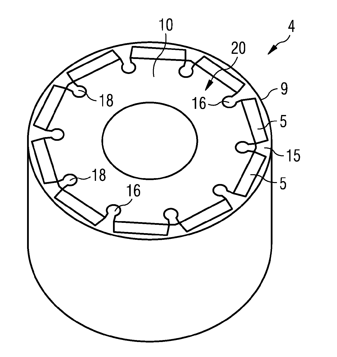
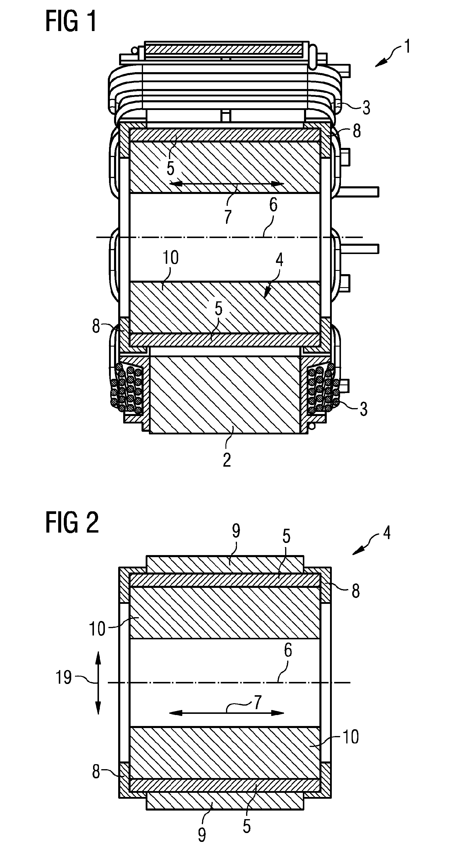
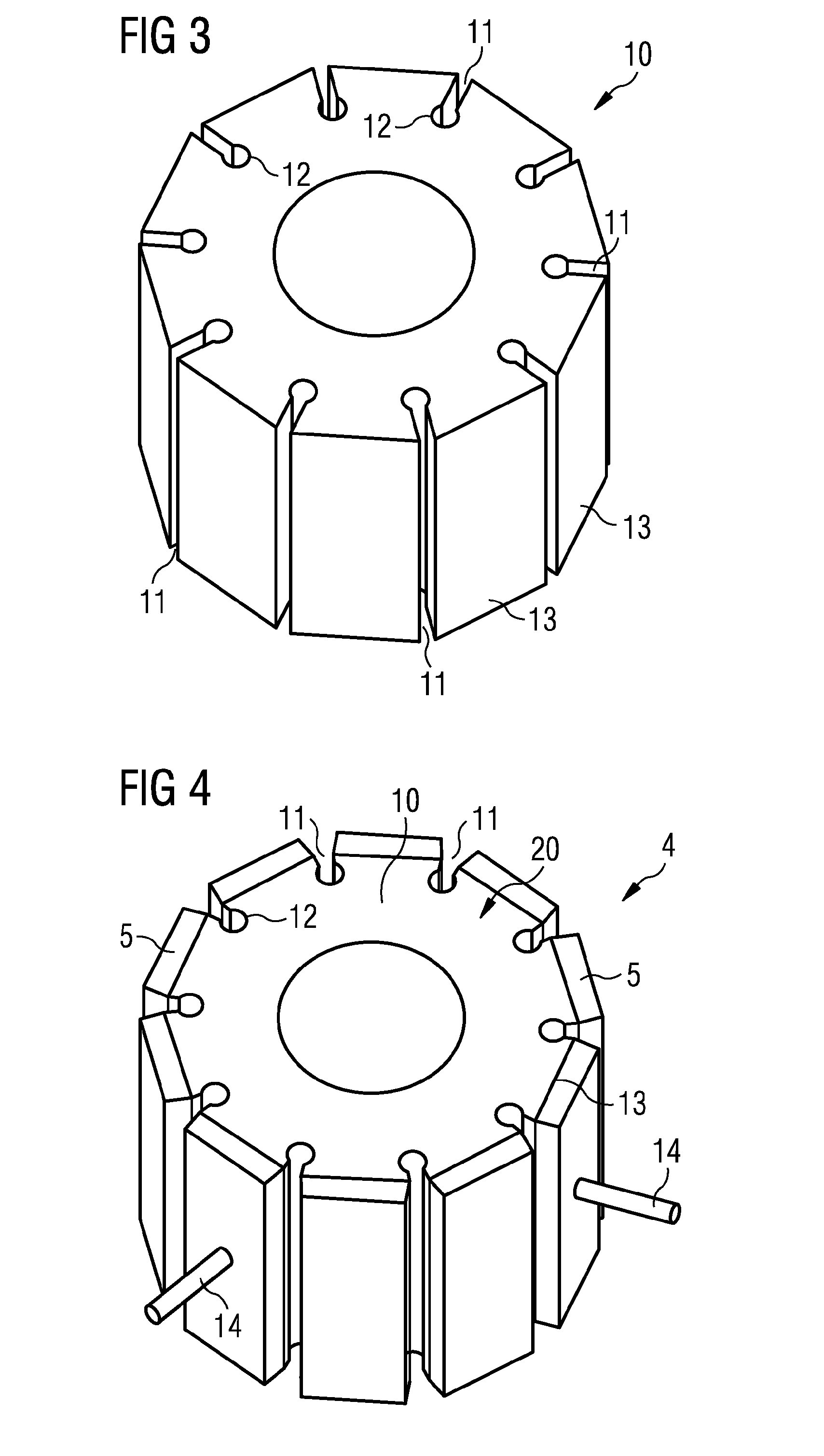
[0023]FIG. 1 shows an electric motor 1 with a stator 2 and with a rotor 4. Electric motor 1 may be a reluctance motor, as it is known. Coils 3 are attached to the stator 2 and can be subjected to a commutated electrical current whereby a magnetic alternating field can be generated. The rotor 4 is mounted rotatably on an axis 6 and has a basic body 10 and permanent-magnetic elements 5. These permanent-magnetic elements 5 are held on the basic body 10 by a joining sleeve 9 and a locking element 8 (FIG. 2). The arrow indicates the axial direction 7 in which, for example, the joining sleeve 9 can be pushed onto the basic body 10. The permanent-magnetic elements 5 are of parallelepipedal form, this being especially cost-effective. However, they may also be of shell-shaped form.

[0024]The set-up of the rotor 4 is illustrated in more detail in FIG. 2. A multiplicity of permanent-magnetic elements 5, which are arranged on the cylindrical outer surface of the basic body 10, are shown. The per...


PUM


Abstract

A rotor for an electric motor, that includes a main body on which a support surface is formed, to which a permanent magnet element is attached. The main body is partially surrounded by a joining sleeve having chamber walls. The chamber walls together with the support surfaces form a chamber in which the permanent magnet element is arranged. The joining sleeve fixes the position of the permanent magnet element in a radial direction on the main body and a locking element is molded onto the main body. The locking element closes the chamber fixing the position of the permanent magnet element in the axial direction on the main body.

Description

CROSS REFERENCE TO RELATED APPLICATIONS[0001]This is a U.S. national stage of application No. PCT / EP2011 / 055389, filed on 7 Apr. 2011. Priority is claimed on German Application No. 10 2010 014 597.1 filed 9 Apr. 2010, the content of which is incorporated here by reference.BACKGROUND OF THE INVENTION[0002]1. Field of the Invention[0003]The invention relates to a rotor for an electric motor, the rotor having a basic body on which is formed at least one bearing surface, to which at least one permanent-magnetic element is attached. The invention relates, furthermore, to a method for producing a rotor for an electric motor.[0004]2. Description of the Prior Art[0005]Rotors for electric motors of the type initially mentioned are known and are used in many different ways. There are different methods for fastening the permanent-magnetic elements to the basic body of the rotor. It is known, for example from DE 10 2005 052 870 A1, to inject a plastic completely around the permanent-magnetic el...

Claims


Application Information

Patent Timeline
IPC IPC(8): H02K1/28
CPCH02K15/03H02K1/278H02K1/28H02K1/02
Inventor BRANDAU, RUDIGERSIEBALD, KURT
Owner VITESCO TECH GMBH
Why Eureka
Try Eureka