
Coal nozzle assembly for a steam generation apparatus

Active Publication Date: 2020-05-21
GENERAL ELECTRIC TECH GMBH
View PDF0 Cites 0 Cited by
  • Summary
  • Abstract
  • Description
  • Claims
  • Application Information

AI Technical Summary

Benefits of technology

[0012]It has been proven advantageous if the inner housing and/or the outer housing have a square or rectangular cross-section. Among other advantages this geometry allows producing the nozzle from sheet metal in a cost-effective way.
[0013]Further advantageou

Problems solved by technology

The resulting partial separation of coal particles and the primary air among other negative effects reduce th

Method used


Image

  • Coal nozzle assembly for a steam generation apparatus
  • Coal nozzle assembly for a steam generation apparatus
  • Coal nozzle assembly for a steam generation apparatus

Examples


Example

DETAILED DESCRIPTION OF THE DRAWINGS

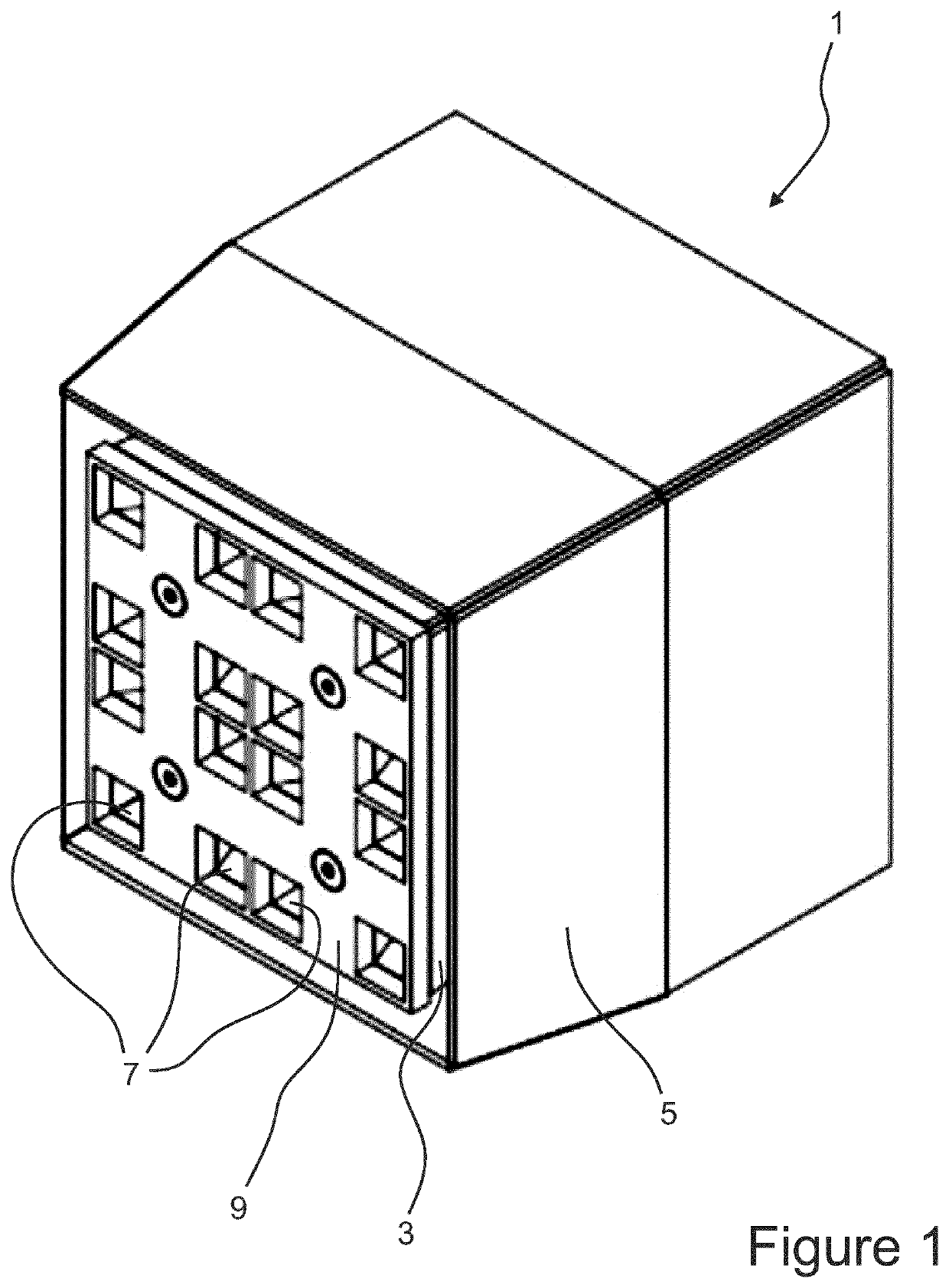
[0025]FIG. 1 illustrates a perspective view of a nozzle tip 1 according to the invention. An inner housing 3 of the nozzle tip 1 is surrounded by an outer housing 5. The space between the outer housing 5 and the inner housing 3 forms a channel for transporting secondary air into a furnace (not shown). The secondary air exits the nozzle tip 1 via a square or rectangular gap between the inner housing 3 and the outer housing 5, thus building a perimeter flow of secondary air. This gap between the inner housing 3 and the outer housing 5 is the exit area of the a.m. channel for transporting secondary air.

[0026]The primary air and the entrained coal particles exit the nozzle tip 1 through openings 7 in a cover plate 9. For reasons of clarity, not all openings 7 have reference numerals. Altogether, there are sixteen (square) openings 7 visible in FIG. 1.

[0027]As can be seen from FIG. 1, the cover plate 9 has a grid-like design dividing an exit face of th...


PUM


Abstract

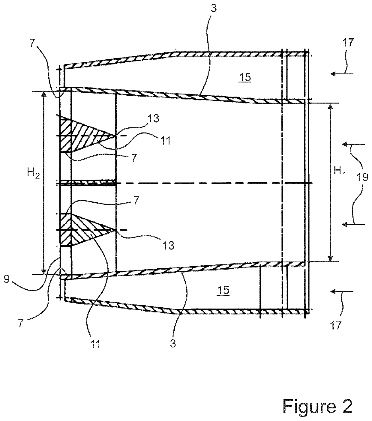
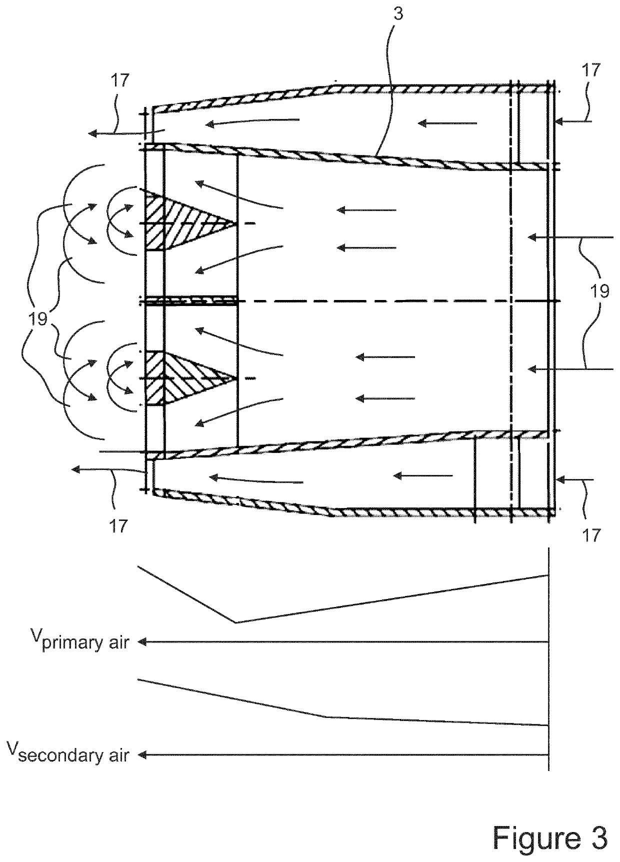
A steam generating system includes a nozzle assembly for pulverized coal and air, the coal nozzle assembly comprises an inner housing (3) for conveying primary air and coal and an outer housing (5) for conveying secondary air to an exit face (13) of a nozzle tip (1), wherein the outer housing (3) and the inner housing (5) are arranged coaxially and limit a channel (15) for the secondary air, wherein the cross-sectional area (AIH) of the inner housing (3) increases towards the exit face (13) of the nozzle tip (1), wherein the cross-sectional area (AOH) of the outer housing (5) decreases towards the exit face (13), and wherein bars (11) are located in the inner housing (3) near the exit face (13) that accelerate the velocity of the primary air and coal particles.

Description

BACKGROUND OF INVENTION[0001]This disclosure relates to a nozzle assembly for a steam generation apparatus for directing the flow of solid particles entrained in a fluid system into a combustor or furnace. It further relates to a steam generating system which comprises a furnace and at least one coal nozzle assembly.PRIOR ART[0002]A solid fueled firing system burns powdered solid fuel, typically coal, blown into a furnace in a stream of air. This furnace is typically a boiler that creates steam for various uses, such as creating electricity.[0003]When the pulverized coal particles are conveyed through the duct work from the coal mill to the coal nozzle assembly by means of primary air they tend to aggregate at various paths. The resulting partial separation of coal particles and the primary air among other negative effects reduce the burning efficiency in the furnace and raise the amount of pollutants in the fuel gas, which is undesirable. Among other pollutants reducing the NOx-Emi...

Claims


Application Information

Patent Timeline
IPC IPC(8): F23C13/06F23C5/02F23D1/00
CPCF23D1/00F23D2201/20F23D2900/00001F23D2201/30F23C13/06F23D2201/10F23C5/02
Inventor SAPANARO, MICHAELVITSE, FREDERICLADUE, RACHELKRAWIEC, JOSEPH
Owner GENERAL ELECTRIC TECH GMBH
Learn More