Fuel Injector

Inactive Publication Date: 2007-10-25
ROBERT BOSCH GMBH
View PDF11 Cites 1 Cited by
  • Summary
  • Abstract
  • Description
  • Claims
  • Application Information

AI Technical Summary

Benefits of technology

[0006] The fuel injector according to the present invention has the advantage over the related art that the internal pressures of the coupler are able to be achieved in a permanent and reliable manner in different loading states of the coupler, the coupler is able to be produced in a simple and cost-effective manner, has a less complex design and is reliable in continuous operation.
[0008] In an advantageous manner, the flexible section is elastic and made from an elastomer, for example. This allows stretching of the flexible section and ensures that it continues to provide sealing with respect to conventional fuels.

Problems solved by technology

Disadvantageous in this known related art is that the preloading by the flexible section changes during the service life of the fuel injector in a disadvantageous manner, the coupler has a complex design and is able to be produced only at great expense due to the many individual components of the coupler.

Method used


Image

  • Fuel Injector
  • Fuel Injector
  • Fuel Injector

Examples


Embodiment Construction

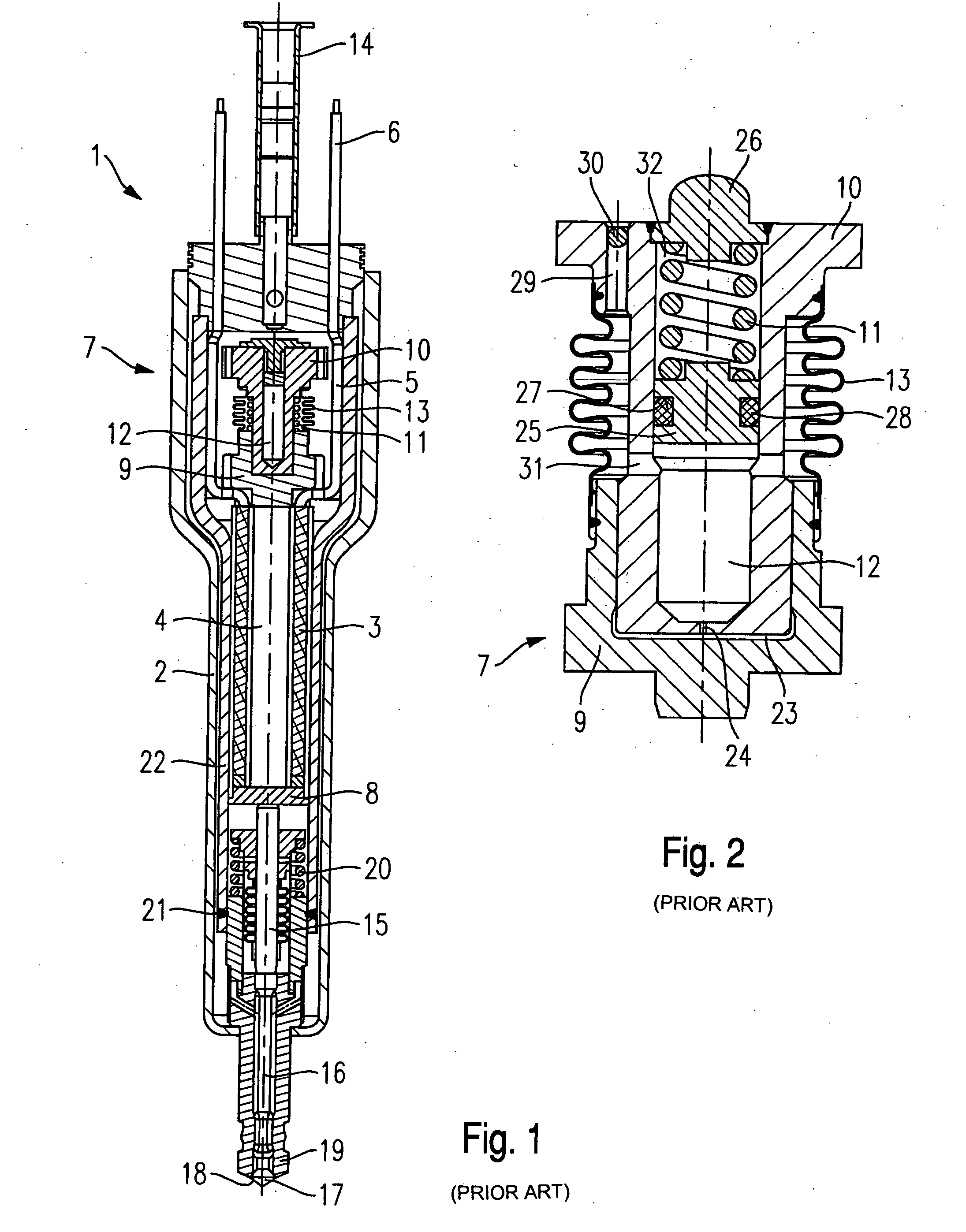
[0021] Before the present invention is described in greater detail with the aid of example embodiments, the essential components of a fuel injector according to the related art shall be briefly explained in FIGS. 1 and 2 for better understanding of the present invention. Identical parts have been provided with matching reference numerals in the figures.

[0022] Fuel injector 1 shown in FIG. 1 is configured as a fuel injector for fuel-injection systems of mixture-compressing internal combustion engines having externally supplied ignition. Fuel injector 1 is particularly suited for the direct injection of fuel into a combustion chamber (not shown) of an internal combustion engine.

[0023] Fuel injector 1 includes a housing 2 in which a piezoelectric or magnetostrictive actuator 4 provided with an actuator extrusion coat 3 is situated. An electrical voltage is able to be supplied to actuator 4 via an electrical line 5 on which an electrical connector 6, which projects beyond housing 2, m...


PUM


Abstract

A fuel injector has a piezoelectric or magnetostrictive actuator, which actuates a valve-closure member cooperating with a valve-seat surface to form a sealing seat. A hydraulic coupler includes a master piston, a slave piston, and a coupler volumeformed in-between. The master piston and the slave piston are axially displaceable with respect to one another. The coupler volume is connected to a compensating chamber via a throttle. A flexible section delimits the compensating chamber at least partially, and the coupler volume, the throttle, and the compensating chamber are filled with a hydraulic medium. At least one spring element directly or indirectly exerts pressure on the flexible section from the outside, via fixed components.

Description

FIELD OF THE INVENTION [0001] The present invention relates to a fuel injector having a piezoelectric or magnetostrictive actuator. BACKGROUND INFORMATION [0002] A system for an adaptive, mechanical tolerance compensation acting in the lift direction for a path transducer of a piezoelectric actuator for a fuel injector is described in published European Patent document EP 0 477 400. In the process, the actuator lift is transmitted via a hydraulic chamber. The hydraulic chamber has a defined leak having a defined leakage rate. The actuator lift is introduced into the hydraulic chamber via a master piston and transmitted to an element to be driven via a slave piston, for example, a valve needle of a fuel injector. [0003] Guided in the master piston is a slave piston, which also seals the master piston and in this way forms the hydraulic chamber. Arranged in the hydraulic chamber is a spring which presses the master piston and the slave piston apart. When the actuator transmits a lifti...

Claims


Application Information

Patent Timeline
IPC IPC(8): F02M51/00F02M51/06F02M61/08F02M61/16F02M63/00
CPCF02M51/0603F02M2200/703F02M61/167F02M61/08
Inventor NOLLER, KLAUSLAND, PETERVOGEL, CHRISTOFHUEBEL, MICHAELGERSCHWITZ, THOMAS
Owner ROBERT BOSCH GMBH
Why Eureka
Try Eureka