Pneumatic tire
a pneumatic tire and tire body technology, applied in vehicle components, transportation and packaging, vehicle rigidity optimization, etc., can solve the problems of radio noise, reducing steering stability, and insufficient support of non-conductive rubber, so as to secure steering stability, maintain rigidity balance, and reduce rolling resistance
- Summary
- Abstract
- Description
- Claims
- Application Information
AI Technical Summary
Benefits of technology
Problems solved by technology
Method used
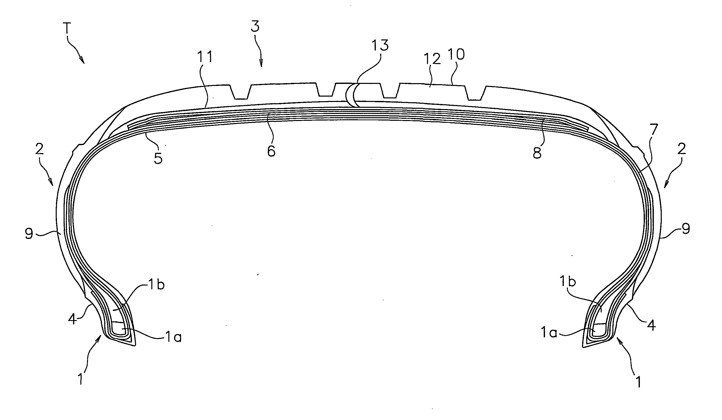
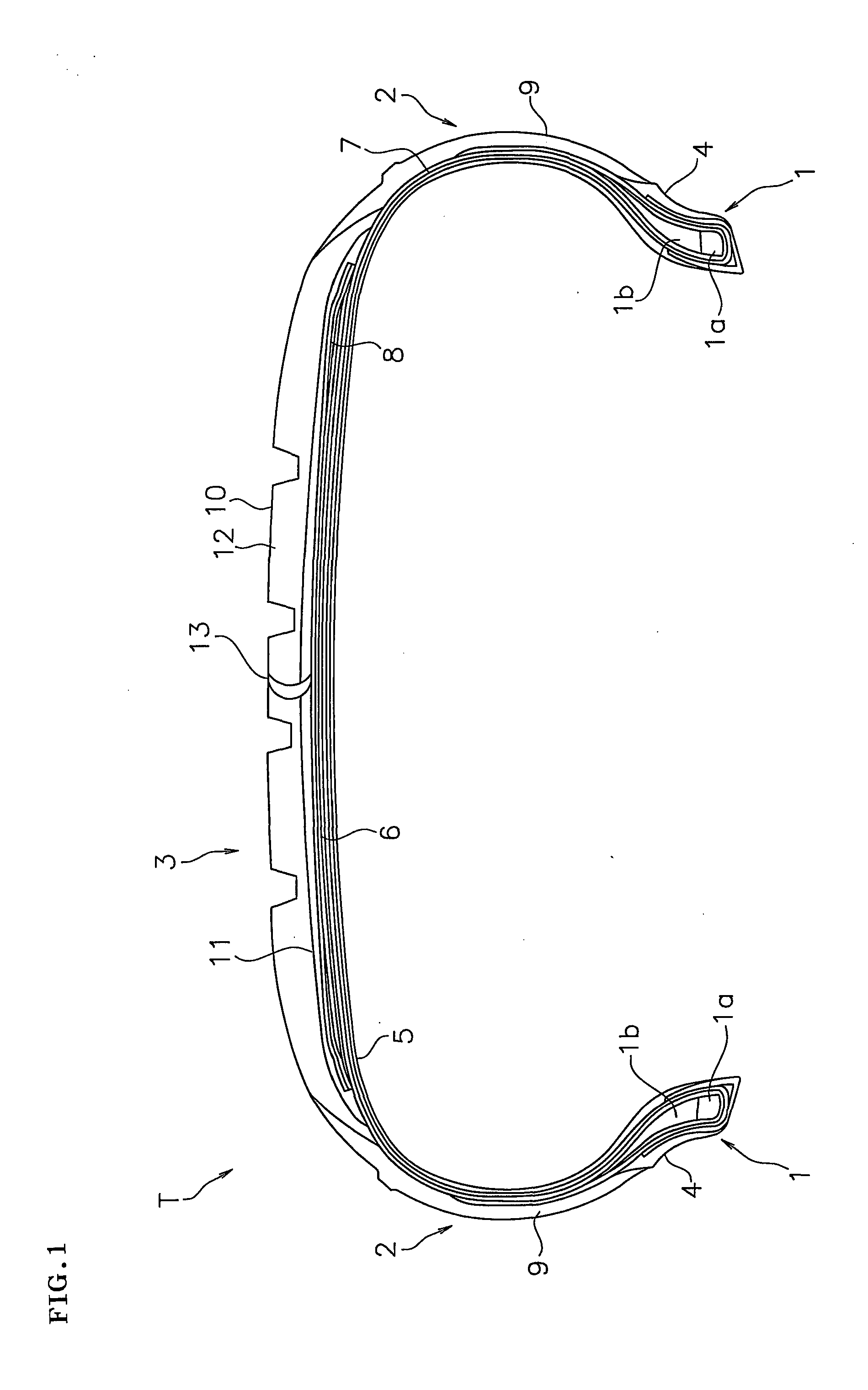
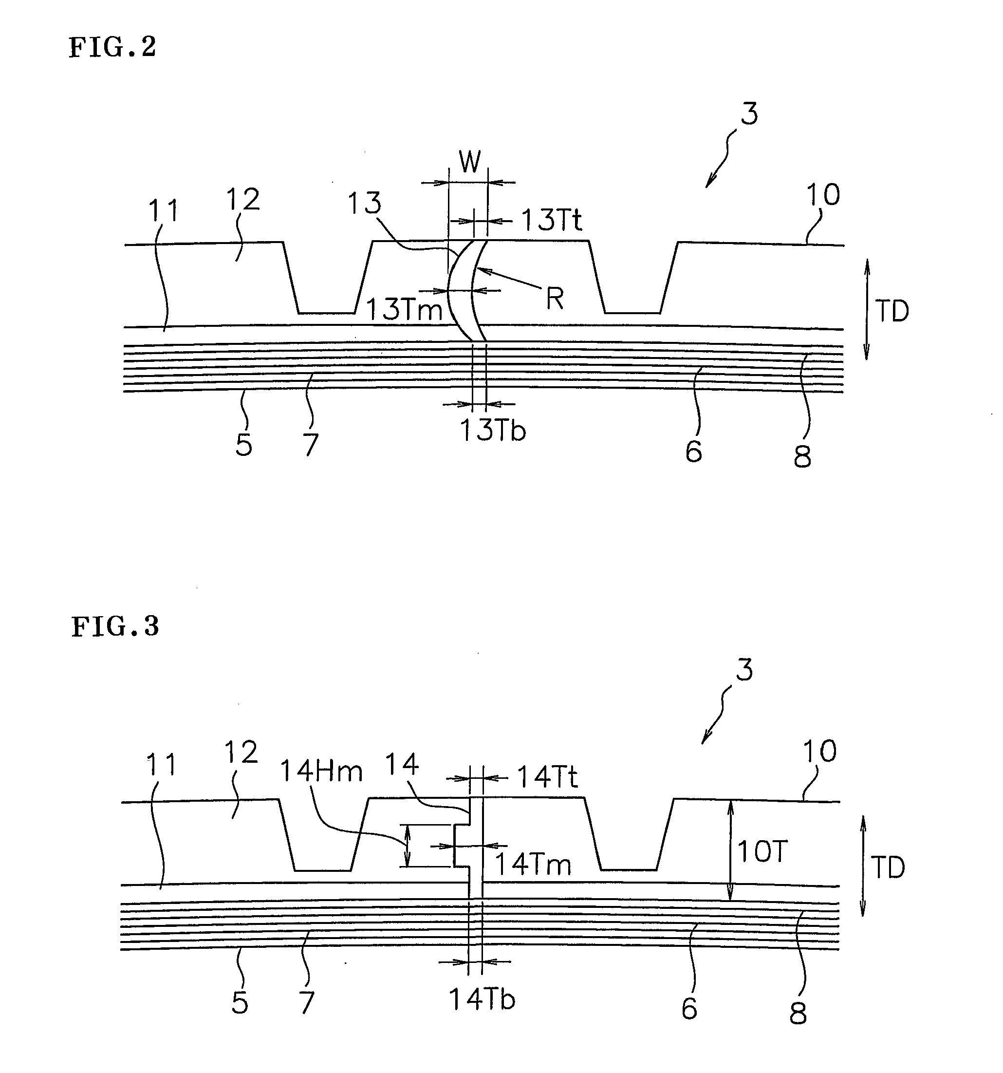
Image

Examples
example
[0049]An example which concretely shows the structure and effect of the present invention will be explained. An evaluation of each of performances is executed as follows.
[0050](1) Steering Stability
[0051]A tire was installed to an actual car (domestic sedan car of 1.5 L class), straight moving travel and cornering travel were performed in a state where a load of one driver riding the car was applied under a pneumatic pressure designated by a vehicle, and an evaluation was carried out according to a feeling test of the driver. The evaluation was carried out by an index number by setting a result of Conventional Example to 100, and larger numerical value indicates more excellent steering stability.
[0052](2) Rolling Resistance
[0053]A rolling resistance at a speed 80 km / h was measured on the basis of an international standard ISO28580 (JISD4234), and an inverse number thereof was calculated. The evaluation was carried out by an index number by setting a result of Conventional Example to...
PUM
 Abstract
Description
Claims
Application Information
 - R&D
- Intellectual Property
- Life Sciences
- Materials
- Tech Scout
- Unparalleled Data Quality
- Higher Quality Content
- 60% Fewer Hallucinations
Browse by: Latest US Patents, China's latest patents, Technical Efficacy Thesaurus, Application Domain, Technology Topic, Popular Technical Reports.
© 2025 PatSnap. All rights reserved.Legal|Privacy policy|Modern Slavery Act Transparency Statement|Sitemap|About US| Contact US: help@patsnap.com