
Panoramic image generation from cbct dental images

Inactive Publication Date: 2013-01-24
CARESTREAM DENTAL TECH TOPCO LTD
View PDF6 Cites 39 Cited by
  • Summary
  • Abstract
  • Description
  • Claims
  • Application Information

AI Technical Summary

Benefits of technology

The present invention integrates the skills of a human operator with computer capabilities to create panoramic images from dental computed tomography images. This combines the operator's creativity, flexibility, and judgment with the computer's speed and accuracy. The technical effect is an improved method for creating better dental images.

Problems solved by technology

It has been found, however, that extracting the contour of the teeth is a very challenging task.
For various reasons, the results shown in the Shah et al. publication demonstrate very limited success in tackling this problem.
However, this method fails to be sufficiently robust for practical use.
However, in practice, it proves to be difficult to select a total of five different threshold values for a proper segmentation operation.
Results obtained from this processing sequence can be disappointing and show poor dissection between the teeth.
However, results have shown that Gao's method may not separate the teeth correctly in many cases.

Method used


Image

  • Panoramic image generation from cbct dental images
  • Panoramic image generation from cbct dental images
  • Panoramic image generation from cbct dental images

Examples


Embodiment Construction

[0025]In the following detailed description of embodiments of the present invention, reference is made to the drawings in which the same reference numerals are assigned to identical elements in successive figures. It should be noted that these figures are provided to illustrate overall functions and relationships according to embodiments of the present invention and are not provided with intent to represent actual size or scale.

[0026]In the context of the present invention, the descriptive term “object of interest” generally indicates an object or a portion of anatomy such as a tooth.

[0027]The term “set”, as used herein, refers to a non-empty set, as the concept of a collection of elements or members of a set is widely understood in elementary mathematics. The term “subset”, unless otherwise explicitly stated, is generally used herein to refer to a non-empty proper subset, that is, to a subset of the larger set, having one or more members. For a set S, a subset may comprise the comp...


PUM


Abstract

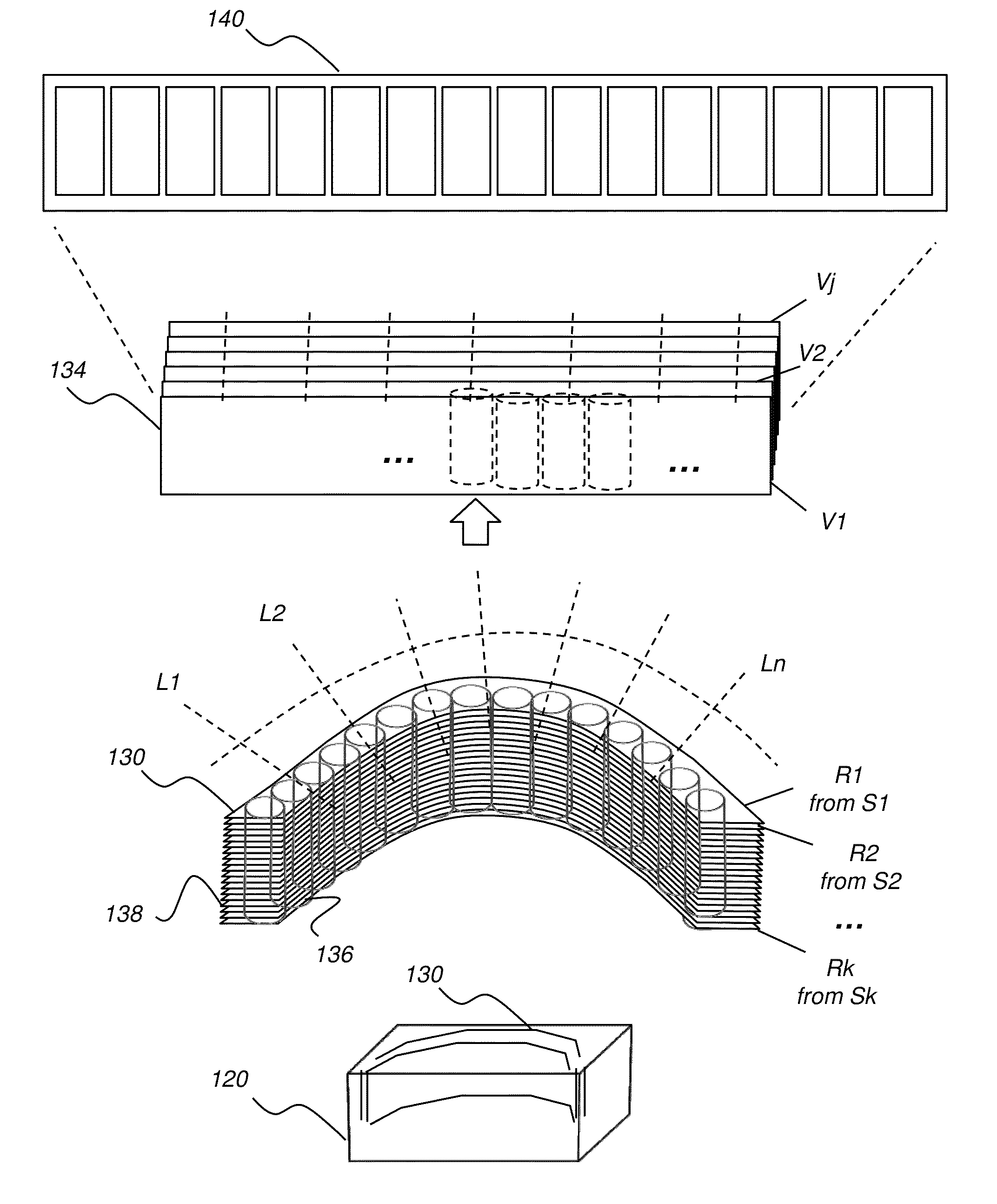
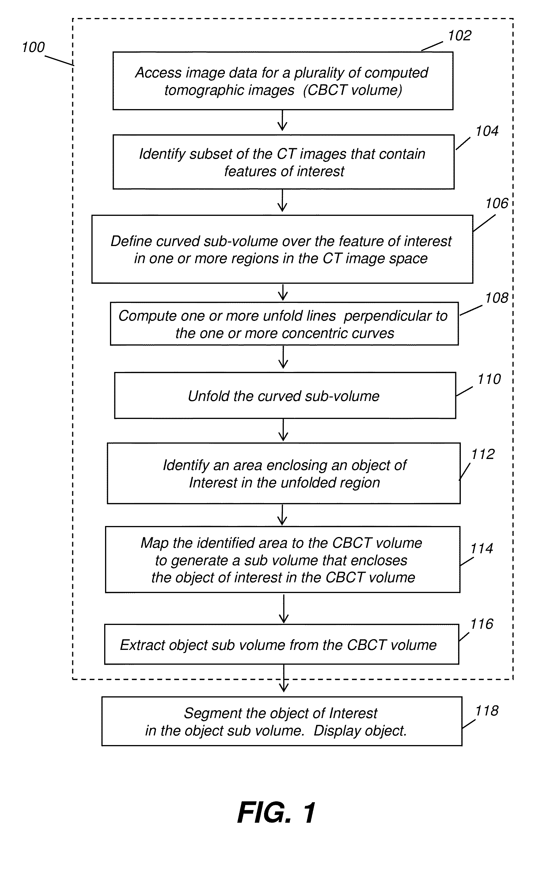
A method for forming a panoramic image from a computed tomography image volume, acquires image data elements for one or more computed tomographic volume images of a subject, identifies a subset of the acquired computed tomographic images that contain one or more features of interest and defines, from the subset of the acquired computed tomographic images, a sub-volume having a curved shape that includes one or more of the contained features of interest. The curved shape is unfolded by defining a set of unfold lines wherein each unfold line extends at least between two curved surfaces of the curved shape sub-volume and re-aligning the image data elements within the curved shape sub-volume according to a re-alignment of the unfold lines. One or more views of the unfolded sub-volume are displayed.

Description

CROSS-REFERENCE TO RELATED APPLICATIONS[0001]This application is a Continuation-in-Part of commonly assigned copending U.S. patent application U.S. Ser. No. 13 / 187,596 filed on Jul. 21, 2011 entitled “METHOD AND SYSTEM FOR TOOTH SEGMENTATION IN DENTAL IMAGES” to Chen et al.FIELD OF THE INVENTION[0002]The present invention relates generally to image processing in x-ray computed tomography and, in particular, to digital CBCT volume three dimensional teeth segmentation.BACKGROUND OF THE INVENTION[0003]Imaging and image processing for computer-aided diagnosis and improved patient care are areas of growing interest to dental practitioners. Among areas of particular interest and significance for computer-aided diagnosis, treatment assessment, and surgery is image segmentation, particularly for tooth regions.[0004]Various approaches have been proposed in recent years to tackle the tooth segmentation problem. For example, Shah et al. in a study entitled “Automatic tooth segmentation using a...

Claims


Application Information

Patent Timeline
IPC IPC(8): G06K9/46
CPCG06K2209/05G06T3/4038G06T3/0031G06V2201/03G06T3/06
Inventor CHEN, SHOUPURAY, LAWRENCE A.INGLESE, JEAN-MARC
Owner CARESTREAM DENTAL TECH TOPCO LTD
Learn More