Forty-five degree dual broad band base station antenna

Active Publication Date: 2013-01-03
INTEL CORP
View PDF4 Cites 31 Cited by
  • Summary
  • Abstract
  • Description
  • Claims
  • Application Information

AI Technical Summary

Benefits of technology

The present invention provides a method for operating a multi-band antenna that has multiple sets of high-band radiating elements. These high-band elements can be located inside or outside of the low-band radiating elements. The method includes providing a first frequency RF communication signal to the low-band array, a second higher frequency RF communication signal with a first power level to the first set of high-band elements, and a second higher frequency RF communication signal with a second power level to the second set of high-band elements. The second power level compensates for increased beamwidth caused by co-location of the first set of high-band elements with the low-band elements. The technical effect of this compensation is improved efficiency and accuracy in beamforming and communication.

Problems solved by technology

Conventional solutions may result in relatively large structures which are typically not favored by local municipalities.

Method used


Image

  • Forty-five degree dual broad band base station antenna
  • Forty-five degree dual broad band base station antenna
  • Forty-five degree dual broad band base station antenna

Examples


Embodiment Construction

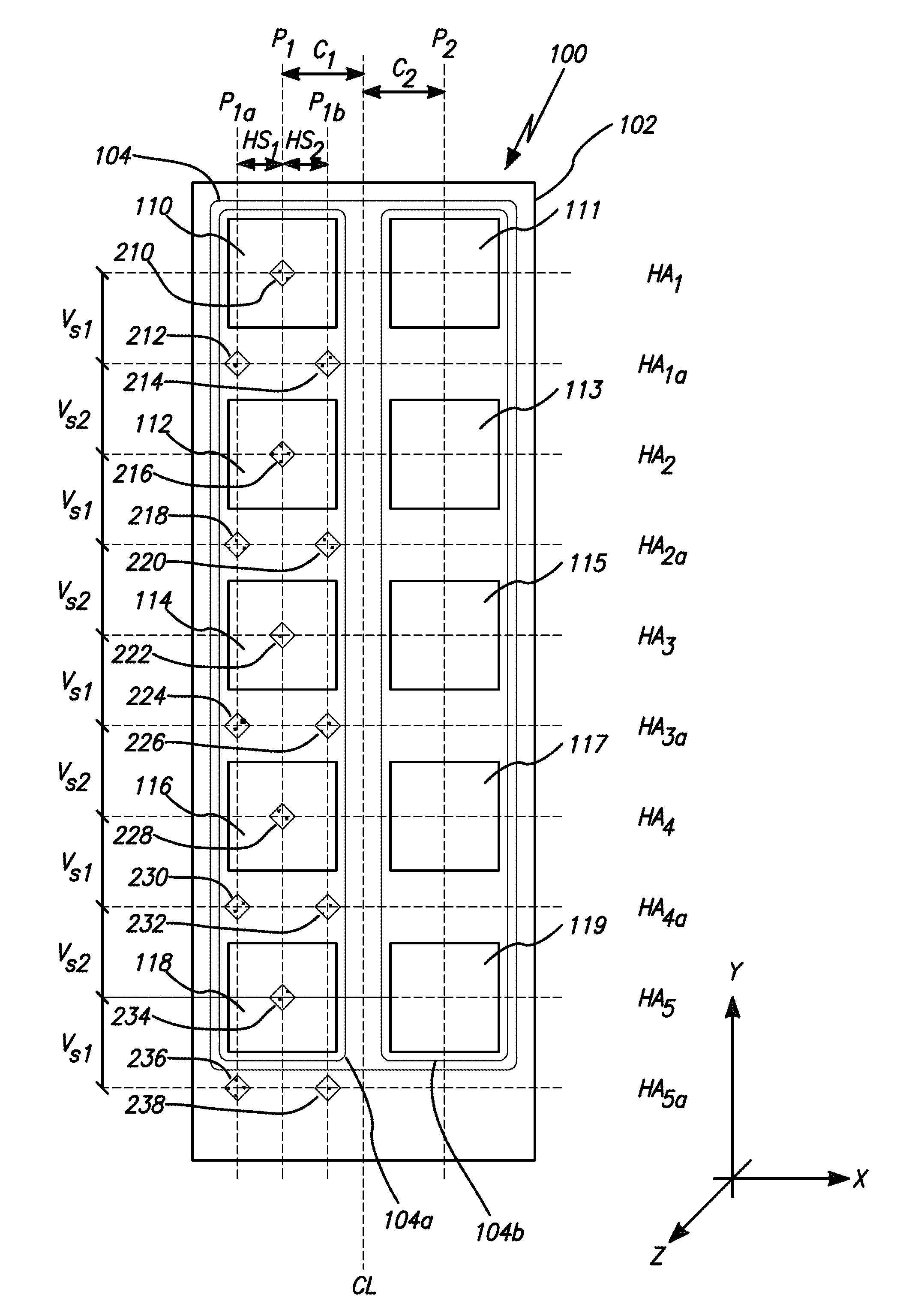
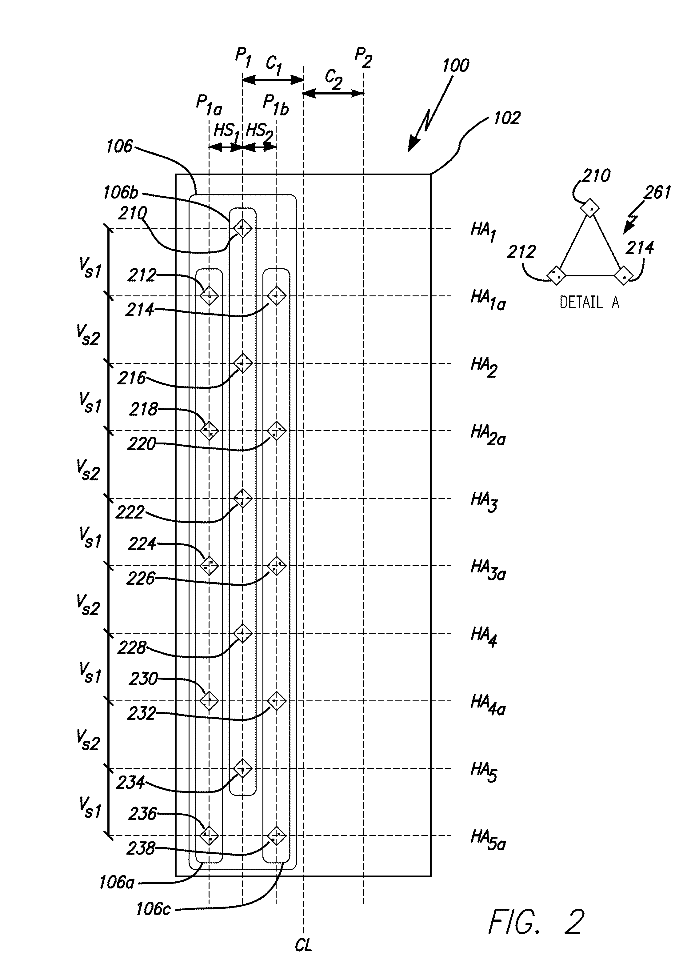
[0027]Embodiments of the invention provide a multiple frequency band, dual cross polarization base station antenna (“BSA”) arrangement exhibiting a narrow azimuth or horizontal plane beamwidth (“HPBW”) of approximately 45 degrees and an operable signal coverage in two non-overlapping frequency blocks. A block may include at least one or more communication bands. For example, a low frequency block may contain FB1=700 LTE and FB2=850 WCDMA, while a high frequency block may include FB3=1900 PCS, FB4=2100 AWS, and FB5=2600 LTE. While providing broadband operation, the antenna system shall be capable of low coupling between different frequency bands while at the same time minimizing the space needed as compared to conventional antennas. A first preferred embodiment of such an antenna may be provided with four RF feed ports. A second preferred embodiment may be capable of operation in a low frequency block and two independent high frequency blocks. It shall be understood that both the for...


PUM


Abstract

The present invention relates to a multiband antenna specifically adapted for use with a Base Station Antenna (“BSA”). The present invention provides narrow azimuth or horizontal beamwidth (“HBW”) having 45 degrees and operational over four frequency bands. The composite antenna topology and associated circuitry described in embodiments achieves reduced antenna installation requirements and allows for ease of network deployment or reconfiguration at reduced cost. Embodiments employ an array of low band radiating elements and two sets of high band radiating elements. The first set is co-located within an array of low band radiating elements. The second set of is offset and outside the low band radiating elements. An RF feed network energizes the first and second set of high band radiating elements to compensate for interference between the high and low band elements.

Description

RELATED APPLICATION INFORMATION[0001]The present application claims priority under 35 U.S.C. Section 119(e) to U.S. Provisional Patent Application Ser. No. 61 / 503,321 filed Jun. 30, 2011, the disclosure of which is incorporated herein by reference in its entirety.BACKGROUND OF THE INVENTION[0002]1. Field of the Invention[0003]The present invention is related in general to radio communication systems and components. More particularly, the invention is directed to antenna arrays for wireless communication networks.[0004]2. Description of the Prior Art and Related Background Information[0005]Composite band antennas may be employed in multiband basestations for mobile communication systems to serve up to four different systems operating simultaneously on four different bands. For example, Global System for Mobile Communication (“GSM”), Digital Cellular Systems 1800 (“DCS1800”), and Universal Mobile Telecommunications System 2100 (“UMTS-2100”) systems currently coexist in Europe, and eme...

Claims


Application Information

Patent Timeline
IPC IPC(8): H01Q19/10H01Q21/12H01Q5/42
CPCH01Q1/246H01Q5/42H01Q21/061H01Q19/104
Inventor TEILLET, ANTHONYKAN, HING
Owner INTEL CORP
Why Eureka
Try Eureka