
Dual polarized three-sector base station antenna with variable beam tilt

a base station antenna and variable beam technology, applied in the field of antennas, can solve the problems of prior-art three-sector antennas not finding a wide application field, bulky antenna systems, and unsatisfactory aesthetics, so as to reduce friction, improve intermodulation, and minimize contact surface

Inactive Publication Date: 2007-03-27
ANDREW LLC
View PDF10 Cites 62 Cited by
  • Summary
  • Abstract
  • Description
  • Claims
  • Application Information

AI Technical Summary

Benefits of technology

[0021]The present invention advantageously provides a compact dual polarized three-sector base station antenna with variable beam tilt in each sector, allowing wireless operators much more flexibility and opportunity to use such an antenna where conventional antennas cannot be used.
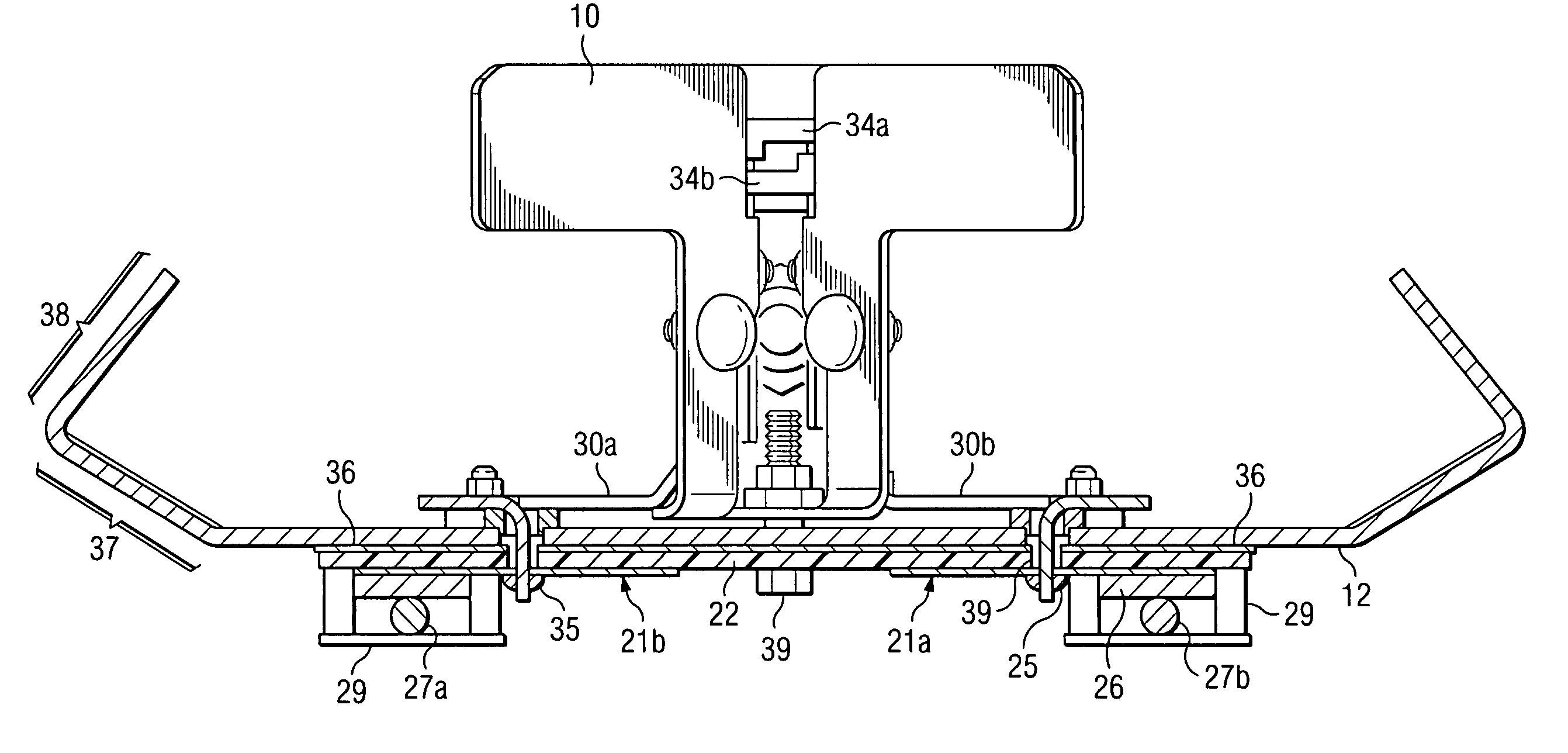
[0022]The present invention advantageously provides a variable phase shifter with very small lateral dimensions, which significantly reduces the diameter of a three-sector antenna. The feed network is located on both sides of the antenna ground plane, and the combination of the cable, microstrip and airstrip lines further reduces the lateral size of the antenna. This design also helps to eliminate parasitic coupling between feed lines, which is especially important for dual polarized antennas with higher gain and a significant number of elements.

Problems solved by technology

This type of antenna system, however, is bulky and is generally considered to be aesthetically unpleasing.
Notably, prior-art three-sector antennas do not find wide field of application.
Conventionally, mechanical down tilt does not work well for a three-sector antenna.
This type of phase shifter has significant lateral dimensions, and cannot be used in a three-sector array without increasing of it's diameter.
Another big issue for every base station antenna is intermodulation (IM).
Another problem with prior dual polarized dipole arrays with variable tilt is beam squint in the horizontal plane (up to 12° with 10° tilt).
As well known in the art, the mutual coupling between crossed dipoles influences correlation of the two orthogonal polarized signals, and can disturb the effect of polarization diversity.
When three antennas are combined together, the effect of mutual coupling becomes even worse.
Another challenge with three-sector antennas is back radiation.

Method used


Image

  • Dual polarized three-sector base station antenna with variable beam tilt
  • Dual polarized three-sector base station antenna with variable beam tilt
  • Dual polarized three-sector base station antenna with variable beam tilt

Examples


Embodiment Construction

[0045]One embodiment of the present invention operates in a Personal Communication System (PCS) in a frequency band 1850–1990 MHz, but which invention is applicable to others frequency bands as well.

[0046]FIG. 1 shows a three-sector base station antenna 1 according to the present invention mounted on a flagpole 2 to make it virtually invisible in the environment. FIG. 1 also illustrates the need and provision of different down tilts for each of beam 3, beam 4, and beam 5, in this case, because the terrain is not flat.

[0047]FIG. 2, 3 illustrate the dual polarized (±45°) three-sector base station antenna 1 with variable sector beam tilts 1 suitable for use in the application shown in FIG. 1 or other similar applications. The antenna 1 is enclosed by a cylindrically shaped radome 6 formed of dielectric material. Metal strips 7 on the radome 6 provide antenna 1 with better port-to-port isolation than without the strips. End cup 8 seals the top of radome 6. Inside the radome 6 are three ...


PUM


Abstract

A dual polarized three-sector base station antenna with variable beam tilt in each sector. The invention advantageously provides a variable phase shifter with very small lateral dimensions which significantly reduces the diameter of a three-sector antenna. The feed network is located on both sides of the antenna ground plane, and the combination of the cable, microstrip and airstrip lines further reduces the lateral size of the antenna. Metal rings on the radome and double-bended ground plane are providing antenna with better cross-polarization and port-to-port isolation.

Description

FIELD OF THE INVENTION[0001]The present invention is related to the field of antennas, and more particularly to dual polarized base station antennas for wireless communication systems.BACKGROUND OF THE INVENTION[0002]In wireless (cellular) communications, an uplink signal at a base station antenna usually fluctuates as a result of fading caused by multiple reflections at buildings and obstacles. To reduce this fading effect, prior art base stations may have an additional antenna for the same sector to provide space diversity. This type of antenna system, however, is bulky and is generally considered to be aesthetically unpleasing. Another known way to reduce fading is through polarization diversity, i.e. reception of signals on two orthogonal polarizations (usually slant polarizations of + / −45°). Polarization diversity allows a decrease in the number of antennas by two times in comparison with space diversity. However, the base station still needs at least three antennas for a three...

Claims


Application Information

Patent Timeline
Patent Type & Authority Patents(United States)
IPC IPC(8): H01Q21/00H01Q1/24H01Q3/26H01Q21/24H01Q25/00
CPCH01Q1/245H01Q25/00H01Q21/24H01Q3/26
Inventor TIMOFEEV, IGORAI, XIANGYANGTEILLET, ANTHONY
Owner ANDREW LLC
Learn More