
Method and apparatus for discharging an energy store in a high-voltage power supply system

Active Publication Date: 2013-01-03
ROBERT BOSCH GMBH
View PDF4 Cites 11 Cited by
  • Summary
  • Abstract
  • Description
  • Claims
  • Application Information

AI Technical Summary

Benefits of technology

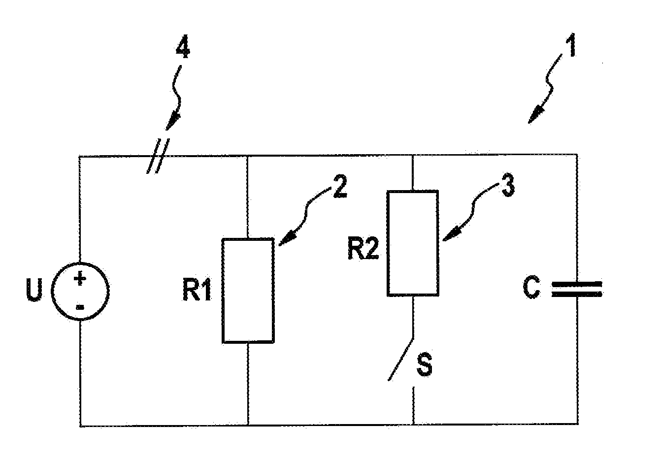
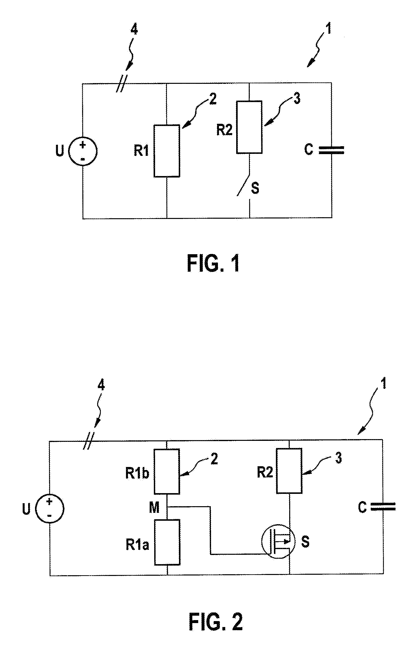
The present invention relates to a device for reducing power loss and preventing damage to discharge resistors in a high-voltage power supply system. The device includes two discharge resistors that are permanently connected in parallel to the energy store of the system. One of the resistors, called the first discharge resistor, consumes power during normal operation of the system. To prevent excessive temperatures that could damage the first resistor, a second discharge resistor can be connected in parallel to the first resistor. This second resistor is only connected when the voltage at the energy store is below a certain threshold. This helps to significantly reduce power loss and heat development, making it possible to use smaller resistors and omit costly heat dissipation measures. The overall resistance value of the first discharge branch is set to have a higher resistance value than the second discharge resistor, which further reduces power loss and prevents damage to the resistors.

Problems solved by technology

Discharge resistors connected permanently in parallel to an energy store of a high-voltage power supply system also consume power during normal operation, which is emitted to the surrounding environment in the form of heat.
The flow of current via the second charge resistor is thus strongly limited in time, and occurs during normal operation of the vehicle only when the motor vehicle is shut off and switched on.

Method used


Image

  • Method and apparatus for discharging an energy store in a high-voltage power supply system
  • Method and apparatus for discharging an energy store in a high-voltage power supply system

Examples


Embodiment Construction

[0018]In the Figures, identical or functionally identical components are identified by the same reference characters.

[0019]FIG. 1 shows a simplified representation of a discharge circuit for a high-voltage on-board electrical system of a hybrid, electric, or fuel cell vehicle. A high-voltage electrical system 1, frequently also referred to as a DC voltage intermediate circuit, has an energy store in the form of an intermediate circuit capacitor C, standardly used as a buffer capacitor for stabilizing the operating voltage of consumers connected to high-voltage on-board electrical system 1. In particular situations, such as after an accident or before maintenance work on the motor vehicle, the high-voltage system can be separated from a high-voltage energy source shown schematically in FIG. 1 as energy source U. In case of a two-voltage on-board electrical system in a motor vehicle, the intermediate circuit voltage supplied by energy source U corresponds for example to a high voltage...


PUM


Abstract

A method and to a device for discharging an energy store, in particular an intermediate circuit capacitor, in a high-voltage power supply system, in particular a DC voltage intermediate circuit in a motor vehicle, a first discharge resistor being connected parallel to the energy store, and a second discharge resistor automatically being connected parallel to the first discharge resistor when a voltage at the energy store falls below a specified threshold value.

Description

[0001]The present invention relates to a method and a device for discharging an energy store, in particular an intermediate circuit capacitor, in a high-voltage power supply system, in particular a DC voltage intermediate circuit in a motor vehicle.BACKGROUND OF THE INVENTION[0002]In hybrid vehicles or motor vehicles having electric drive or fuel-cell drive systems, as a rule voltages are used that can be more than 100 volts. Voltages greater than 60 volts are referred to as “high voltage.” For reasons of personal safety, high-voltage on-board electrical systems in motor vehicles must be capable of being switched off, and must be capable of being discharged within a specified time span. For this purpose, known high-voltage on-board electrical systems include active and / or passive discharging devices. The high-voltage power supply system in a hybrid vehicle or in a motor vehicle having electric or fuel-cell drive—often also referred to as a DC voltage intermediate circuit—includes in...

Claims


Application Information

Patent Timeline
IPC IPC(8): H02J7/00
CPCB60L2240/36H02M2001/322H02M1/32H02M1/322
Inventor VOEGELE, ANDREAS
Owner ROBERT BOSCH GMBH
Learn More