
Power circuit breaker

Inactive Publication Date: 2005-12-06
SIEMENS AG
View PDF16 Cites 0 Cited by
  • Summary
  • Abstract
  • Description
  • Claims
  • Application Information

AI Technical Summary

Benefits of technology

[0007]It is therefore an object of an embodiment of the invention to avoid the disadvantages of the known prior art and to create a power circuit breaker which is distinguished by a design which is simple to realize and is subject to little deformation and is able to withstand high surge currents with low required contact forces.
[0009]The bending resistance of the switching shaft thus contributes to relieving the load on the first enclosure shell such that this first enclosure shell can thus correspondingly be formed such that it is not as robust as the second enclosure shell. This makes it possible to achieve a design for the power circuit breaker which can be realized simply, is subject to little deformation, and has an advantageous geometry. The fact that it is subject to little deformation ensures that it is able to withstand high surge currents with small contact forces being required.
[0010]One preferred refinement of an embodiment of the invention provides for the second enclosure shell to be ribbed. This reduces the deformability of the second enclosure shell and thus of the remaining components which are directly or indirectly connected to it, as a result of which the ability to withstand surge currents is increased.
[0011]In the case of a power circuit breaker in which the switching pole enclosure has pole partitions for the purpose of physically separating adjacent switching poles and in which the two enclosure shells form outer side walls, a further preferred refinement of an embodiment of the invention provides for at least one of the fastening devices to extend in one of the pole partitions and / or one of the side walls. In this manner, there is no need for any additional physical space, in particular any physical space in the switching chambers. Furthermore, no additional insulation is required for the at least one fastening device as a result of this, since the respective pole partition or the respective outer side wall is self-insulating. Tie rods may advantageously be provided as the fastening device.

Problems solved by technology

The bending resistance of the switching shaft thus contributes to relieving the load on the first enclosure shell such that this first enclosure shell can thus correspondingly be formed such that it is not as robust as the second enclosure shell.

Method used


Image

  • Power circuit breaker
  • Power circuit breaker

Examples


Embodiment Construction

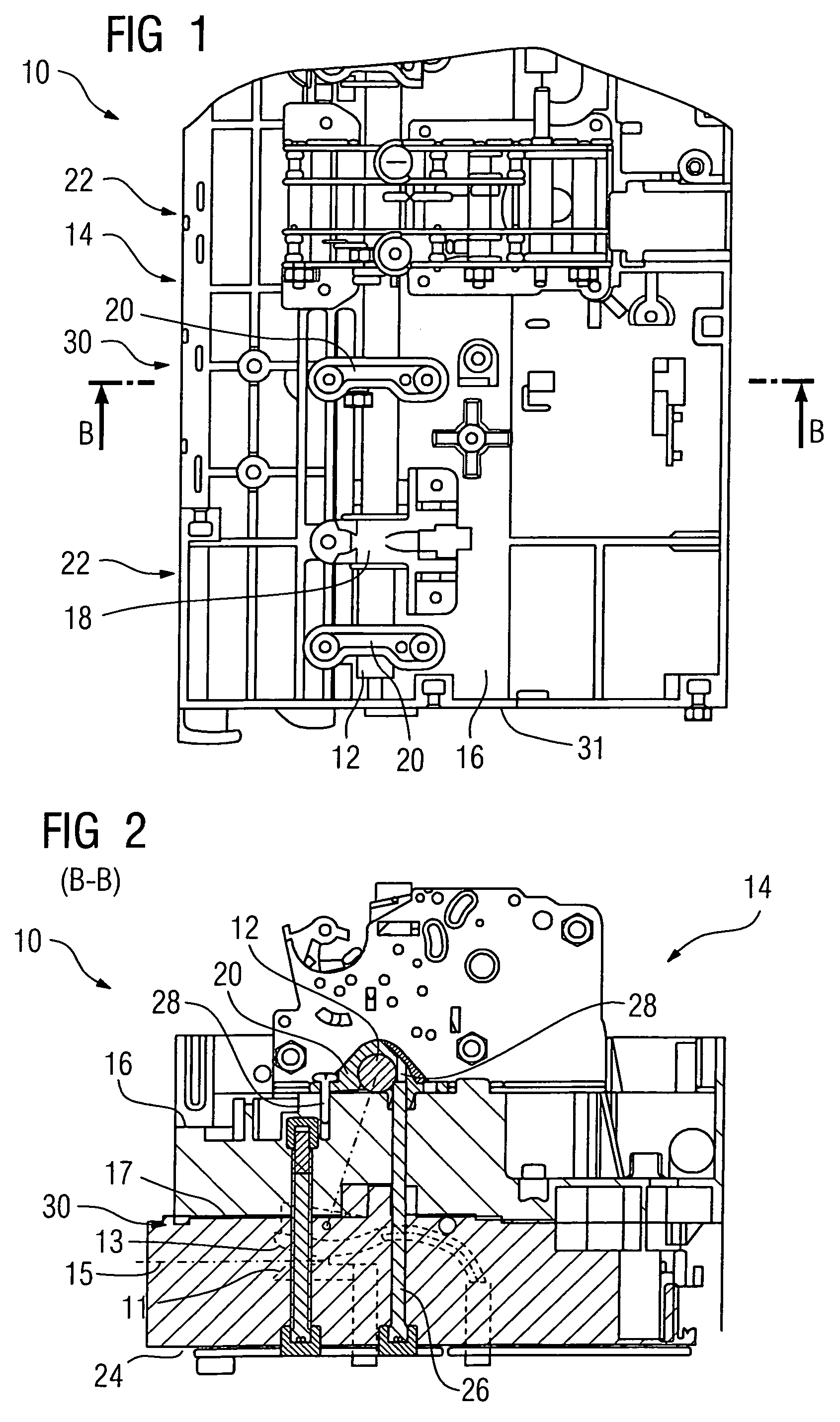
[0015]FIG. 1 shows a detail of an illustration of a power circuit breaker 10 according to an embodiment of the invention. The power circuit breaker 10 includes a multi-part switching pole enclosure 14 (of which only one first enclosure shell 16, which is in the form of a front wall, is visible) three switching poles 22, a switching shaft 12 and switching shaft mounts 18, 20. Pole partitions 30 run between the switching chambers of the switching poles 22 such that each of the switching poles 22 is accommodated in a switching pole chamber. In addition, outer side walls 31 formed by the two enclosure shells 16, 24 contribute to the formation of the outer switching pole chambers.

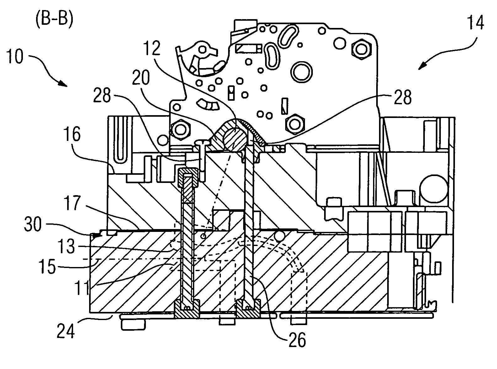
[0016]FIG. 2 shows a section through the power circuit breaker 10 in FIG. 1 along the line B—B, which intersects one of the switching shaft mounts 20 and runs through a pole partition 30. Switching contacts 11 and 13 of the switching poles 22 make contact in a specified contact plane 15 when in the closed positi...


PUM


Abstract

A power circuit breaker includes a switching pole enclosure for accommodating at least one switching pole, whose switching contacts, when closed, rest against one another on a predetermined contact plane. It further includes a switching shaft for transferring drive forces to the at least one switching pole. The switching pole enclosure includes a first and a second enclosure shell, which rest against one another along a separating joint running essentially parallel to the contact plane, and in which the switching shaft is mounted by use of at least two switching shaft mounts held on the first enclosure shell. At least one first and one second fastening device, each serving the purpose of connecting the two enclosure shells, is in each case supported on the one hand on the second enclosure shell and on the other hand on one of the switching shaft mounts.

Description

[0001]The present application hereby claims priority under 35 U.S.C. §119 on German patent application number DE 103 23 094.7 filed May 16, 2003, the entire contents of which are hereby incorporated herein by reference.FIELD OF THE INVENTION[0002]The invention generally relates to a power circuit breaker.BACKGROUND OF THE INVENTION[0003]In the event of a short circuit, high operating forces, such as gas pressure forces and current loop forces, occur in power breakers. These have an effect on the components concerned, in particular the enclosure parts which are screwed to one another and which contain the switching chambers, the contact supports, the switching shaft and the mount and support for the switching shaft which are deformed when subjected to the loads. This deformation, in particular owing to the associated reduction in the contact forces on the interacting switching contacts, reduces the ability of the power breaker to withstand surge currents.[0004]A known measure for avo...

Claims


Application Information

Patent Timeline
IPC IPC(8): H01H71/02H01H71/10
CPCH01H71/0257H01H71/1009H01H2003/326
Inventor DAHL, JOERG-UWEKRUSCHKE, MICHAELLIEBETRUTH, MARC
Owner SIEMENS AG
Learn More