
Apparatus and Methods for Conversion of Silicon Tetrachloride to Trichlorosilane

a technology of apparatus and chlorosilane, which is applied in the direction of silicon compounds, lighting and heating apparatus, gas-gas reaction processes, etc., can solve the problems of large loss of primary raw materials tcs and disposal of byproducts stc, inconvenient addition of heat exchanger equipment for heat recovery, and heavy base pla

Active Publication Date: 2012-12-27
ADVANCED MATERIAL SOLUTIONS LLC
View PDF13 Cites 11 Cited by
  • Summary
  • Abstract
  • Description
  • Claims
  • Application Information

AI Technical Summary

Problems solved by technology

If STC could not be recycled, there would be a huge loss of the primary raw material TCS and a cost for disposal of the byproduct STC.
This equipment has a number of problems.
Furthermore, the retrofitted CVD reactors have a large, heavy baseplate, which is expensive and makes it inconvenient to add heat exchanger equipment for recovery of heat.
Moreover, the heated graphite rods in a retrofitted CVD reactor require a large number of electrical connections.
For example, the reactor may require two to four electrical connections per hairpin, which are all a potential source of rod failure and erroneous ground faults.
Furthermore, CVD reactors have a high radiation heat loss to the shell, wasting large amounts of energy.
The insulation is expensive because it must be made of materials that do not react in a high temperature environment, and it must fit around the outside of the heating rods.
Cheaper insulating materials do not exhibit an adequate lifetime due to reaction with reactant gases at the high temperatures involved.
Also, various key components of the converter have limited lifetimes and must be replaced at regular intervals—including the heating elements, the electrical connections, the insulation, and components of the heat exchanger.
However, such purpose-built systems are not widely used, and are not yet commercially available.

Method used


Image

  • Apparatus and Methods for Conversion of Silicon Tetrachloride to Trichlorosilane
  • Apparatus and Methods for Conversion of Silicon Tetrachloride to Trichlorosilane
  • Apparatus and Methods for Conversion of Silicon Tetrachloride to Trichlorosilane

Examples


constructive examples

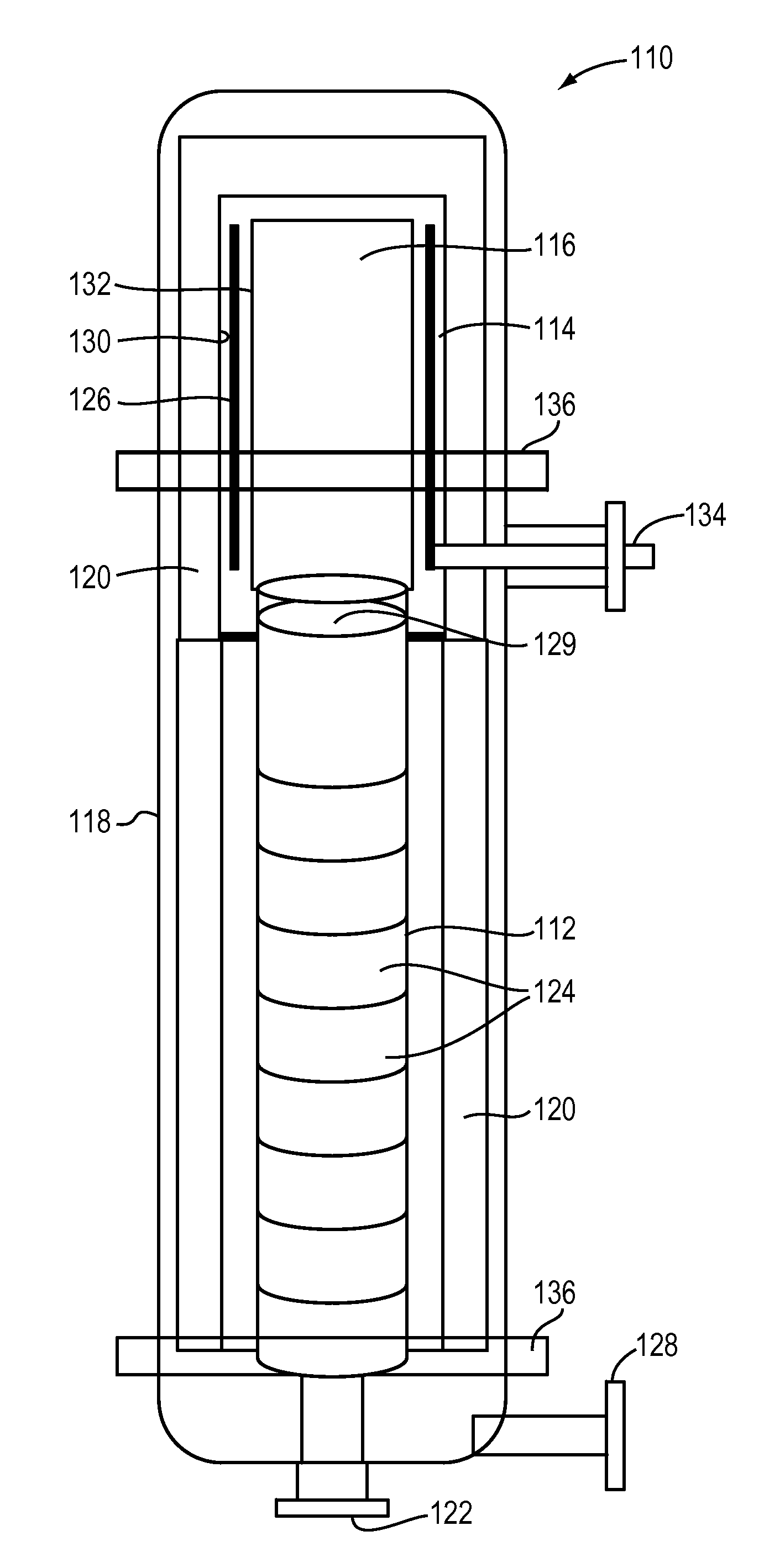
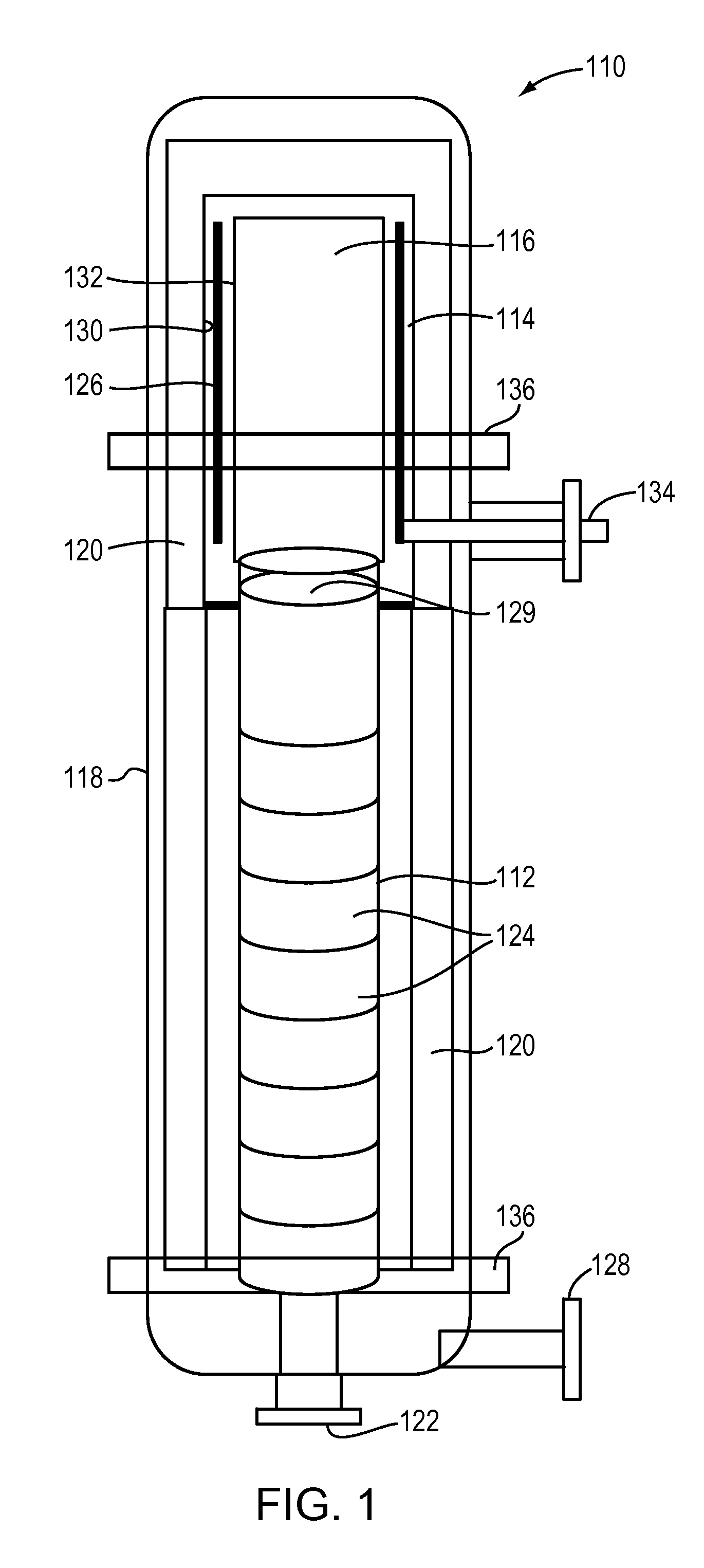
[0081]Numerical modeling techniques were used to simulate the fluid flow and heat transfer within the converter 110. The computational fluid dynamics (CFD) software used for the simulations was ANSYS FLUENT, provided by Ansys, Inc., of Canonsburg, Pa. Input parameters and results for the simulations are provided in Table 1, below.

TABLE 1Input parameters and results for CFD simulations.Gen 2 converter characteristics from Fluent simulations:Input summaryGeometryDetails as available perdesignDivided upon commonsymetryDivided by exchanger blocksMesh sizeVaries by location with in geometryPhysical properties gasFrom DIPPRdatabasePhysical properites solidsPublished from VendorsPressurebarg622Flowkg / hr1930038300Mole ratioH2 / STC22Heat density of heater elementkw / mt356556112232.9InterchangerU overallw / mt2-K413700Hot gas outlet temperatureK10231023Pressure dropBarg1.31.4Heater sectionGas outlet TemperatureK12781280Heater average temperatureK14581565Heater maximum temperatureK15201625Heater m...


PUM


Abstract

The invention relates to apparatus and associated methods for conversion of silicon tetrachloride (STC) to trichlorosilane (TCS). The converter features a relatively thin annular heating zone surrounding a reaction chamber. Within the annular heating zone is a heating element that has an annular conformation about the reaction chamber. The design allows high convective heat transfer, which facilitates the use of lower heating element surface temperatures, prolonging the life of the equipment, reducing capital cost by allowing use of a smaller reactor, and greatly improving heating efficiency. A heat exchanger with a plurality of heat exchanger blocks provides further efficiency.

Description

CROSS-REFERENCE TO RELATED APPLICATIONS[0001]This patent application claims the benefit of U.S. Provisional Patent Application No. 61 / 499,451 and U.S. Provisional Patent Application No. 61 / 499,461, both filed on Jun. 21, 2011, the disclosures of which are hereby incorporated by reference herein in their entireties.FIELD OF THE INVENTION[0002]This invention relates generally to apparatus and methods for hydrogenation of a chlorosilane. More particularly, in certain embodiments, the invention relates to apparatus and methods for conversion of silicon tetrachloride (STC) to trichlorosilane (TCS).BACKGROUND OF THE INVENTION[0003]Chemical vapor deposition (CVD) reactors are used to produce polycrystalline silicon (polysilicon), the key raw material used in silicon-based solar wafers and cells. Polysilicon is also used to make semiconductor wafers for microelectronic applications. The most widely used method for producing polysilicon is the Siemens reactor process, which has been in exist...

Claims


Application Information

Patent Timeline
IPC IPC(8): C01B33/107B01J19/00
CPCC01B33/1071F28F7/02B01J19/0013B01J2219/00159B01J2219/0002B01J2219/00085B01J2219/00094B01J19/0053Y02P20/10B01J2219/00135B01J19/24B01J12/00B01J2219/00103B01J12/005
Inventor FAHRENBRUCK, SCOTTHAZELTINE, BRUCESCHWEYEN, ANDREWSKINNER, SHAWN
Owner ADVANCED MATERIAL SOLUTIONS LLC
Learn More