Steam iron

a technology of steam iron and steam chamber, which is applied in the field of steam iron, can solve the problems of dramatic drop in steam rate, and achieve the effects of reducing condensation rate, reducing water volume, and minimizing waves inside the dosing chamber

Inactive Publication Date: 2012-12-27
KONINKLIJKE PHILIPS ELECTRONICS NV
View PDF8 Cites 8 Cited by
  • Summary
  • Abstract
  • Description
  • Claims
  • Application Information

AI Technical Summary

Benefits of technology

[0008]In accordance with the invention, there is provided a steam iron comprising a housing that includes a water tank, a steam chamber and a pressure equalization conduit. The pressure equalization conduit equalizes the steam pressure between the steam chamber and the water tank. The housing includes an airing means. The steam iron is further provided with a mechanism for selectively allowing air into the water tank through the airing means. The air that is selectively let into the water tank, during the intervals between steaming, prevents under-pressure in the water tank that occurred due to the condensation of steam, thereby resulting in consistent steaming performance. Without this kind of concept, the steam rate would drop drastically over a period of time due to steam condensation in the water tank creating a vacuum. This concept prevents replacement of steam by steam and instead replaces part of the condensed steam by air. This keeps the partial pressure of steam lower in the space above the water and therefore further reduces the condensation rate and keeps the system steaming at a healthy rate.
[0009]According to another embodiment of the invention, the water tank is divided into a dosing chamber and a water reservoir by means of a partition wall. Separation of the water reservoir and the dosing chamber by the partition wall minimizes the waves inside the dosing chamber because of the smaller volume of water in the dosing chamber as compared to the entire tank. This ensures more consistent steaming as well as prevents the water reaching the pressure equalization conduit. The partition wall disallows waves and sloshing in the rest of the water tank to disturb the dosing chamber. This separation also keeps the heat restricted only to the dosing chamber.
[0010]According to a further embodiment, the dosing chamber is three to eight times smaller than the water reservoir. As a result, only a small amount of steam is used for pressure equalization. This minimizes rapid heating up of the entire water tank.
[0011]According to a preferred embodiment, the dosing chamber and the water reservoir are connected to each other by a means for communication. When the means for communication is opened, water can flow freely from the water reservoir to the dosing chamber.
[0013]According to another embodiment, the mechanism for selectively allowing air includes a spring loaded plunger. This acts as an actuator to open or close the pressure equalization conduit and the means for communication between the dosing chamber and water reservoir inversely. This provides a user friendly control of activating the pressure equalization phenomenon.
[0016]According to still yet another embodiment of the invention, the mechanism for selectively allowing air into the water tank is provided with a steam trigger. The steam trigger opens / closes the pressure equalization conduit and the airing means into the water reservoir simultaneously, but inversely. When the steam trigger is actuated, the pressure equalization conduit is opened and water dripping onto the soleplate is replaced by steam from the soleplate. Part of this steam condenses inside the dosing chamber creating an under-pressure. When the iron is rested and the steam trigger is released, the pressure equalization conduit is closed and any under-pressure caused by steam condensation cannot be replaced by steam from the soleplate. Since the airing means is now open, air rushes in and compensates for the under-pressure by pushing water into the dosing chamber. Further, during ironing, as the airing means is closed, the water reservoir cannot receive air, the water in the dosing chamber remains at a constant level thus keeping the steam rate constant for a significant part of the ironing session. This minimizes the water waves in the rest of the water tank due to vacuum above the water level as air is not allowed into the water reservoir while steaming is done.

Problems solved by technology

Without this kind of concept, the steam rate would drop drastically over a period of time due to steam condensation in the water tank creating a vacuum.

Method used


Image

  • Steam iron
  • Steam iron
  • Steam iron

Examples


Embodiment Construction

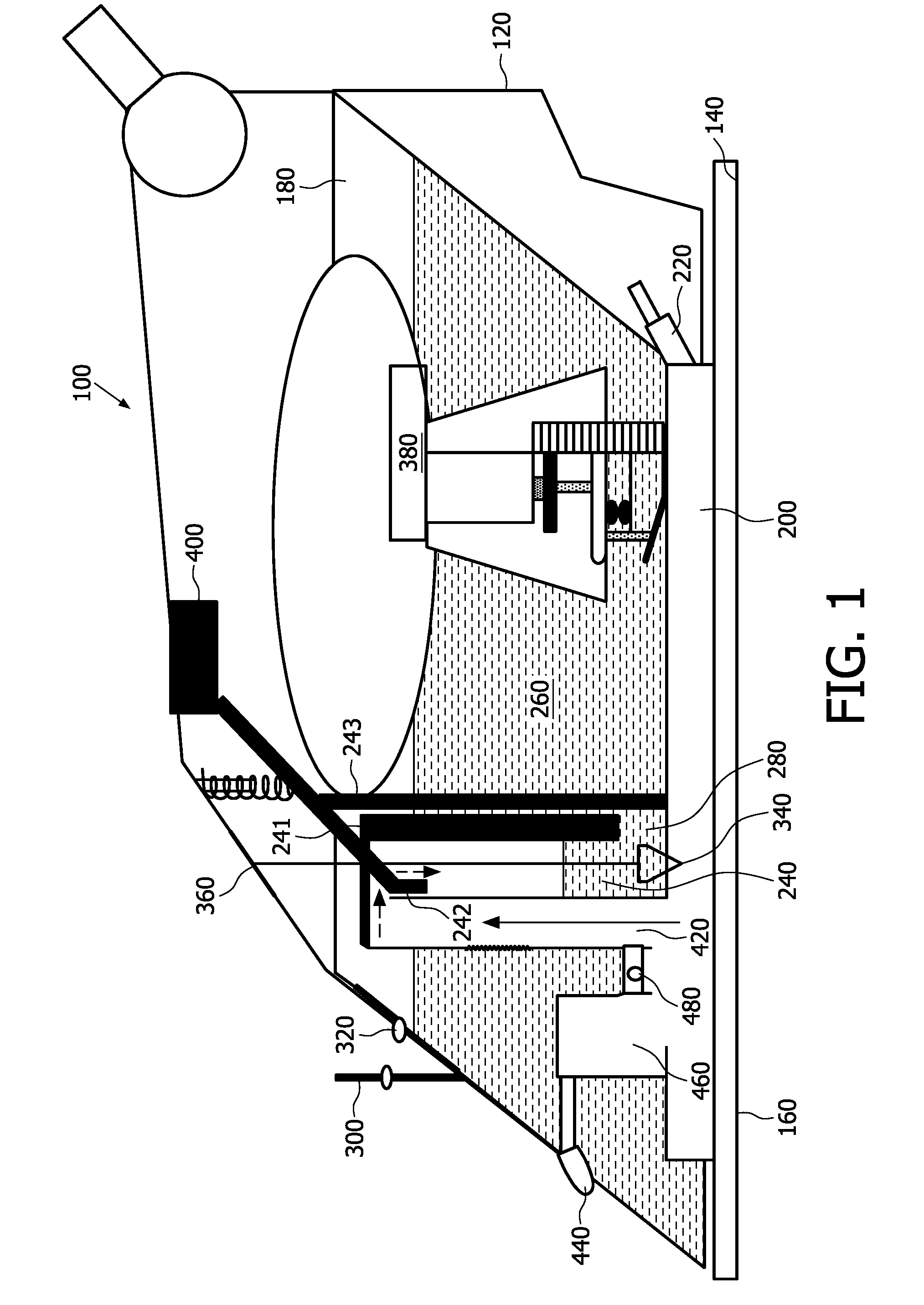
[0022]The present invention will be described with respect to particular embodiments and with reference to certain drawings but the invention is not limited thereto. Any reference signs in the claims shall not be construed as limiting the scope. The drawings described are only schematic and are non-limiting. In the drawings, the size of some of the elements may be exaggerated and not drawn to scale for illustrative purposes. Where the term “comprising” is used in the present description and claims, it does not exclude other elements or steps. Where an indefinite or definite article is used when referring to a singular noun e.g. “a” or “an”, “the”, this includes a plural of that noun unless something else is specifically stated.

[0023]Furthermore, the terms first, second, third and the like in the description and in the claims, are used for distinguishing between similar elements and not necessarily for describing a sequential or chronological order. It is to be understood that the te...


PUM


Abstract

A steam iron (500) comprises a housing (520) that includes a water tank (580), a steam chamber (600) and a pressure equalization conduit (760). The housing (520) includes an airing means (660). The steam iron is further provided with a mechanism for allowing air selectively into the water tank (580). The mechanism comprises a steam trigger (680) that is arranged to close or open the pressure equalization conduit (760) and the airing means (660) inversely. The mechanism may also comprise a spring loaded plunger or an electronic hand sensor.

Description

FIELD OF THE INVENTION[0001]This invention relates to a steam iron, more particularly to a pressure equalized steam iron.BACKGROUND OF THE INVENTION[0002]For a steam iron with a dosing point, water is introduced drop by drop from a water tank into a heated steam chamber. The steam, thus generated, passes out through steam outlet openings of a sole plate and comes into contact with a garment to be ironed. When the iron is placed on the garment, there is a restriction to steam flow and pressure builds up in the steam chamber. In order to equalize the pressure difference between the steam chamber and the inside of the water tank, the water tank and steam chamber are connected to each other by means of a pressure equalization tube. In such irons a constant steam rate is maintained as if the iron were freely suspended.[0003]However, such systems have some practical issues such as steam condensation and overheating of the water tank. When the water in the water tank of the steam iron is m...

Claims


Application Information

Patent Timeline
Patent Type & Authority Applications(United States)
IPC IPC(8): D06F75/14D06F75/18
CPCD06F75/18
Inventor JANAKIRAMAN, CHANDRA MOHANVALIYAMBATH KRISHNAN, MOHANKUMARKUIPER, STEIN
Owner KONINKLIJKE PHILIPS ELECTRONICS NV
Why Eureka
Try Eureka