Methods and systems for exhaust gas recirculation cooler regeneration

a technology of recirculation cooler and exhaust gas, which is applied in the direction of electrical control, process and machine control, etc., can solve the problems of increasing emissions, increasing pressure drop across the egr cooler as well as the temperature of the gas exiting the cooler, and decreasing so as to increase the effectiveness increase the efficiency of the egr cooler, and reduce the effect of egr flow

Active Publication Date: 2012-12-20
GE GLOBAL SOURCING LLC
View PDF7 Cites 66 Cited by
  • Summary
  • Abstract
  • Description
  • Claims
  • Application Information

AI Technical Summary

Benefits of technology

[0004]In such an embodiment, the temperature of the EGR cooler may be controlled based on the fuel distribution among the donor cylinder group and the non-donor cylinder group. For example, when a fuel injection quantity to the donor cylinder group is decreased, an exhaust gas temperature of the donor cylinder group may correspondingly decrease, thereby decreasing a temperature of EGR flow and thus the EGR cooler. In this manner, the EGR cooler may be regenerated, as particulate build-up in the EGR cooler hydrolyzes due to the low temperature such that it may break off in the exhaust flow. Further, when a fuel injection quantity to the donor cylinder group increases, the exhaust gas temperature of the donor cylinder group may correspondingly increase, thereby increasing a temperature of EGR flow and thus the EGR cooler. In this way, the EGR cooler may be regenerated, as particulate build-up in the EGR cooler may be removed by the high temperature exhaust flow. Thus, the EGR cooler may be regenerated under high and / or low exhaust temperature conditions such that the effectiveness of the EGR cooler may increased or maintained.

Problems solved by technology

In such an example, fouling of the EGR cooler may occur when particulate matter (e.g., soot, hydrocarbons, oil, fuel, rust, ash, mineral deposits, and the like) in the exhaust gas accumulates within the EGR cooler, thereby decreasing effectiveness of the EGR cooler and increasing a pressure drop across the EGR cooler as well as temperature of the gas exiting the cooler, resulting in increased emissions and decreased fuel efficiency.

Method used


Image

  • Methods and systems for exhaust gas recirculation cooler regeneration
  • Methods and systems for exhaust gas recirculation cooler regeneration
  • Methods and systems for exhaust gas recirculation cooler regeneration

Examples


Embodiment Construction

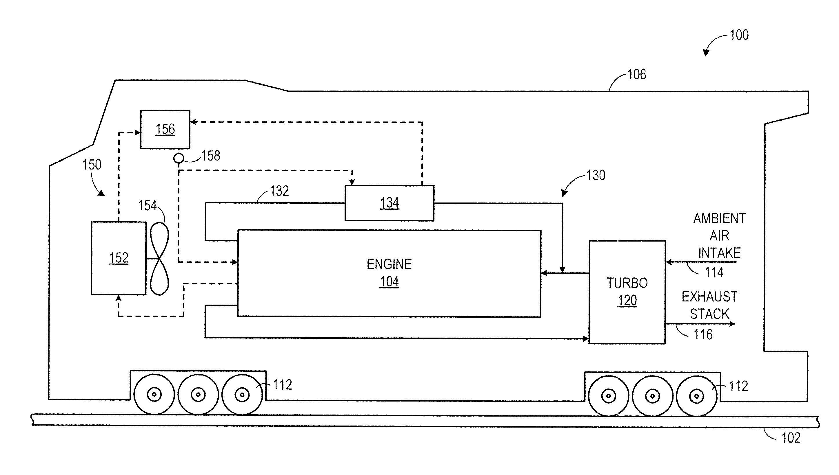
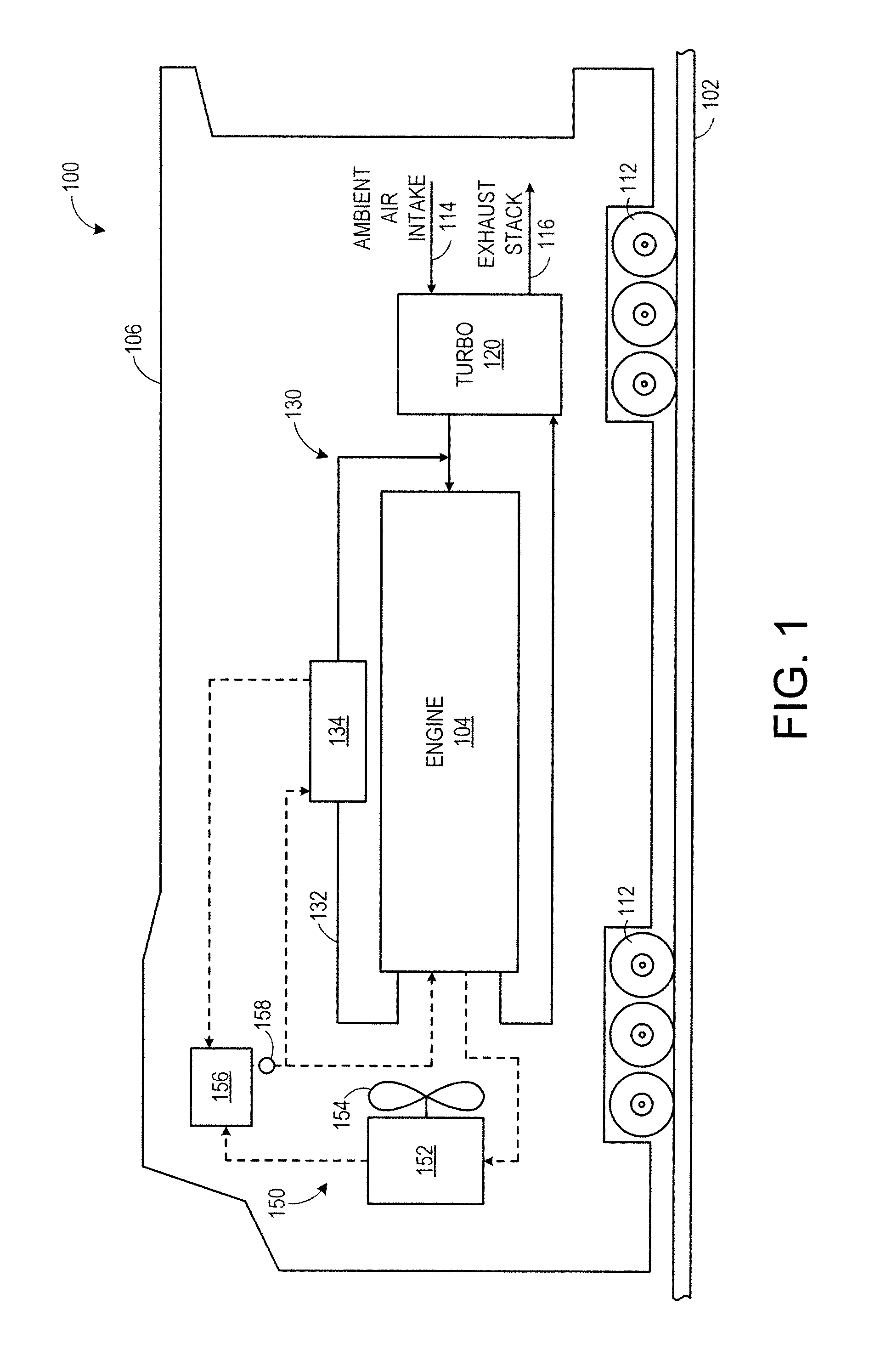
[0015]The following description relates to various embodiments of methods and systems for regenerating an exhaust gas recirculation (EGR) cooler. The EGR cooler may be part of an EGR system coupled to an engine in a vehicle, for example. One example method includes, routing exhaust gas from a donor cylinder group of the engine to an intake passage of the engine through the EGR cooler, routing exhaust gas from a non-donor cylinder group of the engine to an exhaust passage of the engine, and adjusting fuel distribution among the donor cylinder group and the non-donor cylinder group responsive to a temperature of the exhaust gas recirculation cooler. As used herein, donor cylinders refer to cylinders in which their exhaust is routed exclusively to the intake manifold, at least under some configurations, while non-donor cylinders refer to cylinders in which their exhaust is routed, eventually, to atmosphere. It should be appreciated that, as described herein, exhaust from donor cylinder...


PUM


Abstract

Various methods and systems are provided for regenerating an exhaust gas recirculation cooler. One example method includes, routing exhaust gas from a donor cylinder group of an engine to an intake passage of the engine through the exhaust gas recirculation cooler, routing exhaust gas from a non-donor cylinder group of the engine to an exhaust passage of the engine, and adjusting fuel distribution among the donor cylinder group and the non-donor cylinder group responsive to a temperature of the exhaust gas recirculation cooler.

Description

FIELD[0001]Embodiments of the subject matter disclosed herein relate to regenerating an exhaust gas recirculation cooler in an exhaust gas recirculation system coupled to an internal combustion engine.BACKGROUND[0002]Engines may utilize recirculation of exhaust gas from an engine exhaust system to an engine intake system, a process referred to as exhaust gas recirculation (EGR), to reduce regulated emissions. In some examples, a group of one or more cylinders may have an exhaust manifold that is exclusively coupled to an intake passage of the engine such that the group of cylinders is dedicated, at least under some conditions, to generating exhaust gas for EGR. Such cylinders may be referred to as “donor cylinders.” Further, some EGR systems may include an EGR cooler to reduce a temperature of the recirculated exhaust gas before it enters the intake passage. In such an example, fouling of the EGR cooler may occur when particulate matter (e.g., soot, hydrocarbons, oil, fuel, rust, as...

Claims


Application Information

Patent Timeline
Patent Type & Authority Applications(United States)
IPC IPC(8): F02D41/00
CPCF02D41/0065F02D41/008F02D41/0087F02D41/08F02D41/0055F02D41/405F02D13/0219Y02T10/44Y02T10/47F02D41/065F02M26/43F02M26/05F02M26/50F02M26/28F02M26/33F02M26/47Y02T10/40
Inventor KLINGBEIL, ADAMPRIMUS, ROYEASTER, MICHAELPETERS, ERIC DAVID
Owner GE GLOBAL SOURCING LLC
Why Eureka
Try Eureka