Direct acting end link

Inactive Publication Date: 2012-12-20
ILLINOIS TOOL WORKS INC
View PDF11 Cites 1 Cited by
  • Summary
  • Abstract
  • Description
  • Claims
  • Application Information

AI Technical Summary

Benefits of technology

[0008]The direct acting end links disclosed herein include grommets to be positioned on opposite sides of a strut mounting pad and a rod extending through the grommets and mounting pad. At an inner end, the rod includes a collar and holds a washer or bearing against one of the grommets and at the outer end the rod holds a washer against the other grommet and has an end nut attached thereto. By locating and interconnecting various groups of these structures, the locations of relative rotation between parts can be predetermined for better control in minimizing wear and noise. By compressing the grommets into and against the strut mounting pad, the grommets can expand and compensate for dimensional changes as wear occurs.

Problems solved by technology

When a direct acting stabilizer is provided on a steerable strut, the connection is somewhat complicated in that the link used to connect the stabilizer bar to the strut must withstand and accommodate not only vertical movement of the strut, but also rotational movement of the strut when the vehicle is steered right or left, in addition to the twisting moment provided on the stabilizer bar during operation.
However, boots are sometimes easily worn, cut or cracked, and can allow the ingress of contaminants and thereafter trap the contaminants when present in the joint.
Further, due to the rotational nature of the end of a ball joint link, assembly and installation have been difficult in that the fastened end must be driven into place, and rotation of the end makes it difficult to hold in proper position.
Further, ball joint links have been susceptible to corrosion due to wear, and when worn or corroded tend to fail or operate poorly, resulting in noise or other problems.
However, simple linear end links can not be used in many installations of direct acting suspensions on steerable struts due to the rotational movement at the connecting joint.

Method used


Image

  • Direct acting end link
  • Direct acting end link
  • Direct acting end link

Examples


Embodiment Construction

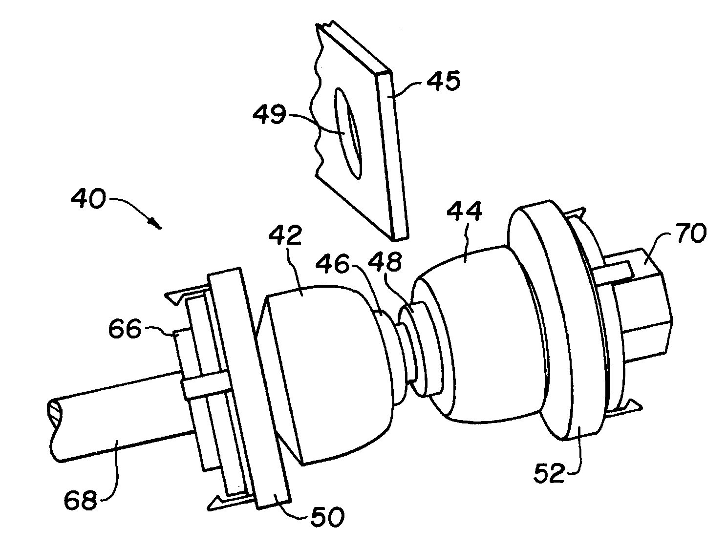
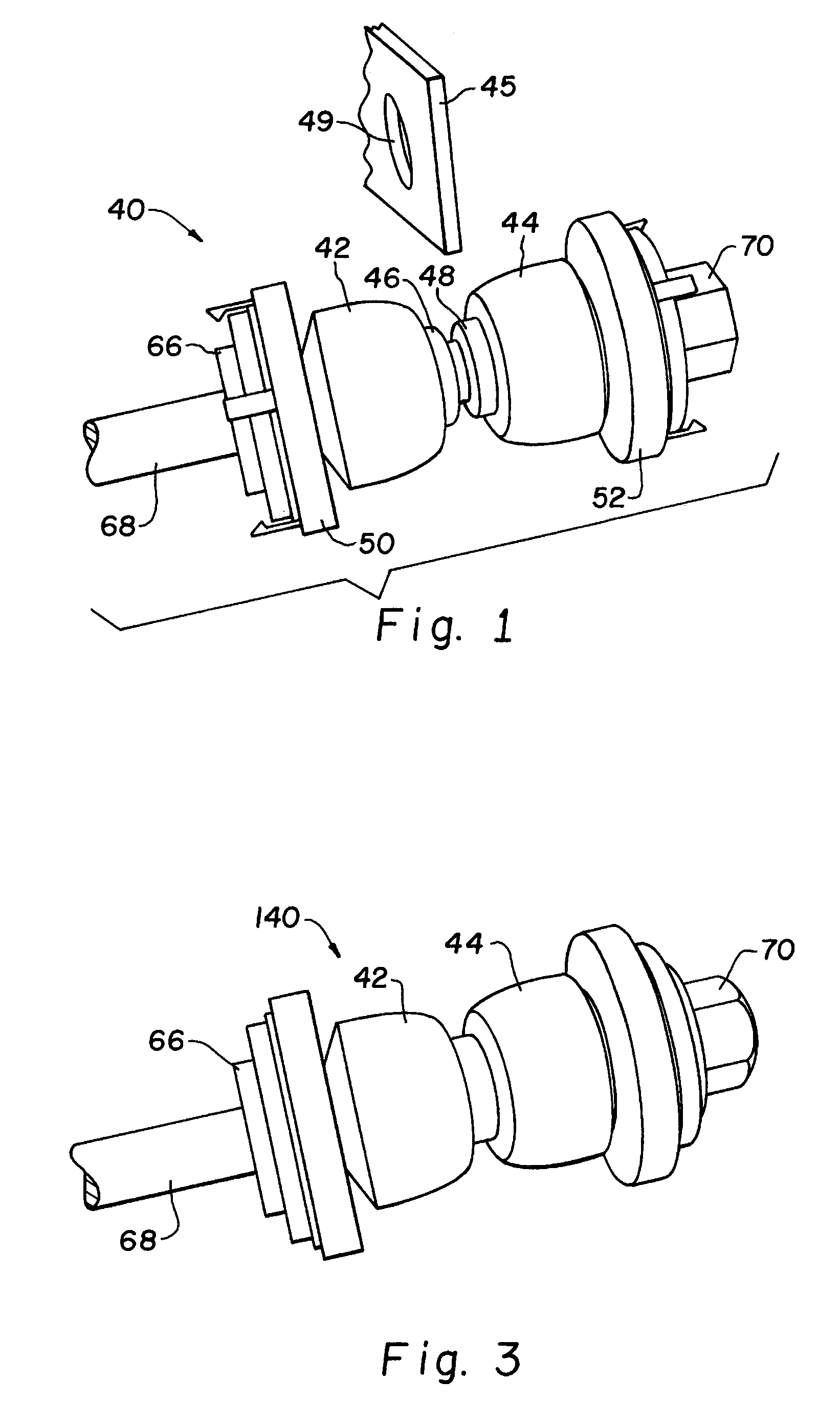
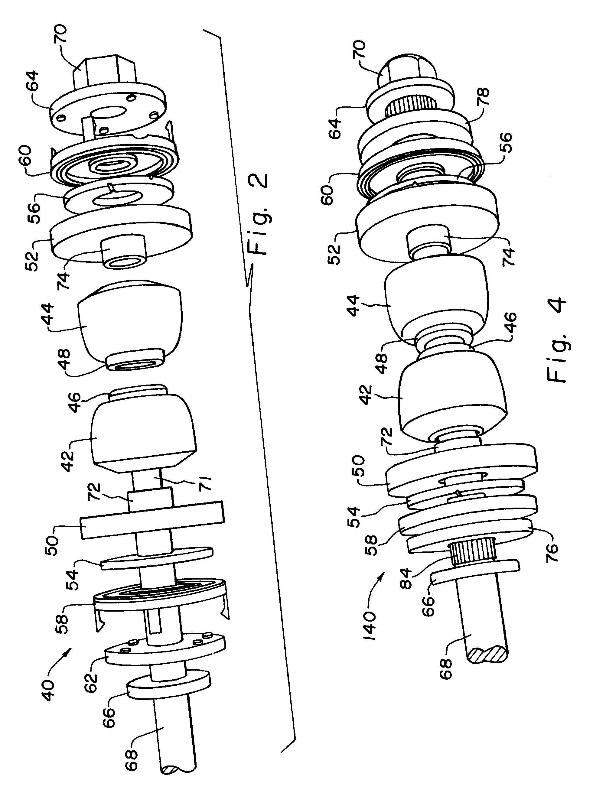
[0032]Referring now more particularly to the drawings and to FIGS. 1 and 2 in particular, a direct acting end link 40 is shown. End link 40 includes a strut connecting end having first and second grommets 42, 44 that are to be positioned and installed on opposite sides of a mounting pad 45 or other point of attachment to a strut. Grommets 42, 44 include confronting, projecting collars 46, 48 of reduced a diameter that are received in and engage opposite sides of a through hole 49 in mounting pad 45. Bearing assemblies are provided adjacent each grommet and include bearing races 50, 52 bearings 54, 56 bearing races 58, 60 and washers 62, 64. Washer 62 confronts a fixed collar 66 on a link rod 68. On a distal end of link rod 68, a nut 70 secures the assembly by engagement with threads 71 of rod 68. Washer 64 and nut 70 can be provided as a unitary assembly. Bearing races 50, 52 include race collars 72, 74 that are received in and engage grommets 42, 44. Rod 68 extends through grommets...


PUM


Abstract

An end link suitable for connecting a direct acting stabilizer bar to a steerable strut includes a rod having first and second grommets thereon. Bearing assemblies are provided adjacent the grommets and include portions thereof connected to for rotation with the grommets and other portions thereof independently rotatable relative to the grommets.

Description

CROSS-REFERENCE TO RELATED APPLICATIONS[0001]The present application claims the benefits of U.S. Provisional Application Ser. No. 61 / 317,314 filed Mar. 25, 2010.FIELD OF THE INVENTION[0002]The present invention relates generally to suspension systems in automobiles, and, more particularly to end links associated with stabilizer bars, control arms and struts in automobile suspension systems, particularly steerable strut type suspension systems.BACKGROUND OF THE INVENTION[0003]It is known to provide automobile suspension systems with a variety of different suspension system configurations for controlling handling, comfort and performance. For example, it is known to provide vertical struts to counteract vertical deflection from bumps, body roll and the like. In some configurations the strut is attached within the overall steering system whereby the strut also rotates as the vehicle is steered. Such configurations are known as “steerable strut suspensions”.[0004]Stabilizer bars are kno...

Claims


Application Information

Patent Timeline
IPC IPC(8): B60G21/055
CPCB60G21/0551Y10T403/32606B60G2204/418B60G2204/1224B60G2204/422B60G2204/4404B60G2206/427
Inventor TROTTER, JASON K.MARK, DENNIS M.FIELD, TROY S.
Owner ILLINOIS TOOL WORKS INC
Why Eureka
Try Eureka