Opening roller housing for an open-end spinning device, device for an opening roller housing and procedure for modernizing spinning devices

Inactive Publication Date: 2005-04-14
RIETER INGOLSTADT SPINNEREIMASCHENBAU AG
View PDF2 Cites 2 Cited by
  • Summary
  • Abstract
  • Description
  • Claims
  • Application Information

AI Technical Summary

Benefits of technology

[0006] The present purpose, in accord with the invention, is to be achieved by a disintegrator roll housing having an insert extending itself up to the area of the contaminant separation opening of the disintegrator roll housing. Further, when seen in the axial direction, in relation to the disintegrating roll, the insert forms at least partially the circumferential wall of the disintegrator roll housing in the area of the contamination separation opening. By the use of an invented insert, a disintegrator roll housing, in a simple way, can be made to accommodate itself to various spinning conditions. Further, a disintegrator roll housing now in accord with the state of the technology can be modernized by means of the procedure of the invented procedure.
[0015] The fastening means, for example, are in the form of bolt borings or the like. By means of the design, wherein the insert in the area of the contamination separation covers the edges of the disintegrator roll, the advantageous achievement is, that no fibers can migrate in this area too far outside of the surface prepared roll. In the case of a favorable formation, the forklike projections impinge on an abutment, whereby they lie on the disintegrator roll housing. In this way, an exact positioning of the insert is possible.

Problems solved by technology

This type of construction of a disintegrator roll housing brings with it the disadvantage that, following the entry of the fiber band by a suction condition, which suction extends itself from the housing of the rotor to that of the disintegrator, a large volume of air is pulled in.
This apparatus has, however, the general disadvantage that, in reference to the actually required air, excessive air is continually fed into the disintegrator roll housing.
The result of this is that the incoming air itself can lead to difficulties within the disintegrator roll housing.
Large cross-sectional openings in the area of the air flow entering the disintegrator roll housing do not yield optimal contamination combing-out and removal conditions.
Such excess air leads, for example, to entrained particle dissipation, since the air exits from the disintegrator roll housing in an uncontrolled manner and carries with it fibers, which aggregate in the area of the spinning machine.
This action results in disturbances in the operation of the machine.
The disintegrator roll housings in accord with the state of the technology have the disadvantage that the contamination separation can vary as to quantity, however, the known inserts are not designed to bring about a conformation of the disintegrator roll housings to the varying loads.
The result of this is that the known disintegrator roll housings cannot be made to suit different fiber materials and other spinning conditions.
Further, with the conventional segments, the zone of the contamination separation is not designed, so that the disintegrator rolls are covered, particularly about their edges.
Moreover, the size of the contamination separation openings can be changed only insufficiently to meet optimal requirements, and especially the location of the openings in relation to the fiber feed (feed opening in the disintegrator roll housing) cannot be altered.

Method used


Image

  • Opening roller housing for an open-end spinning device, device for an opening roller housing and procedure for modernizing spinning devices
  • Opening roller housing for an open-end spinning device, device for an opening roller housing and procedure for modernizing spinning devices
  • Opening roller housing for an open-end spinning device, device for an opening roller housing and procedure for modernizing spinning devices

Examples


Embodiment Construction

[0021] Reference will now be made in detail to the presently preferred embodiments of the invention, one or more examples of which are shown in the figures. Each example is provided to explain the invention, and not as a limitation of the invention. In fact, features illustrated or described as part of one embodiment can be used with another embodiment to yield still a further embodiment. It is intended that the present invention cover such modifications and variations.

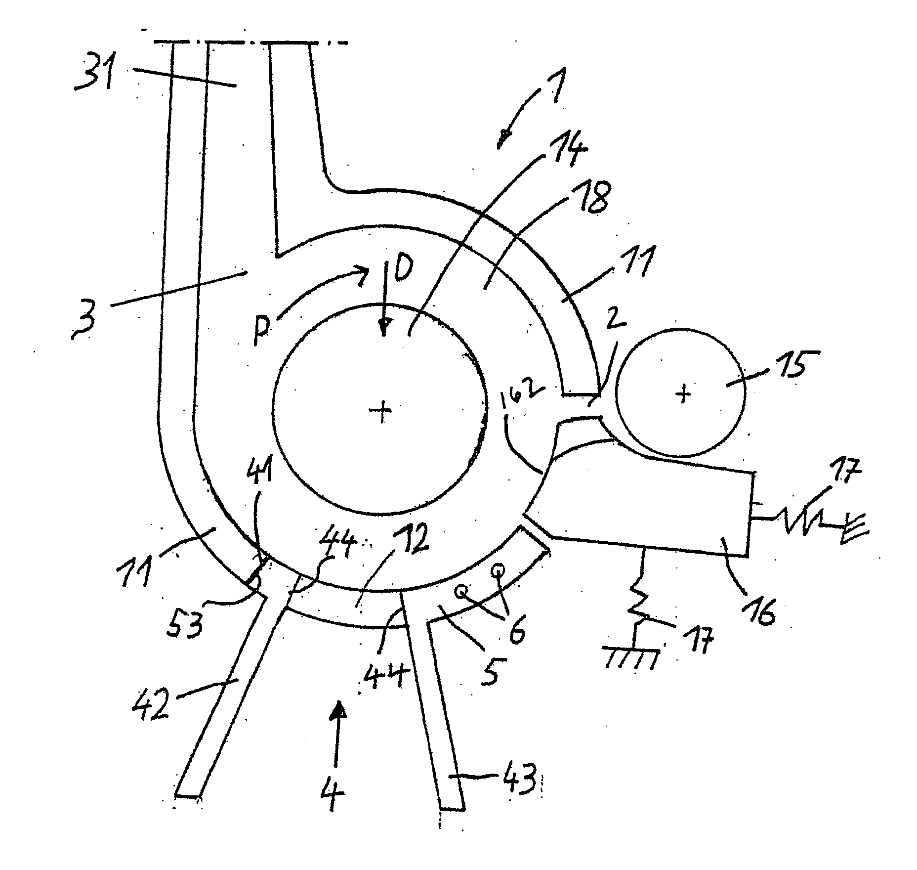
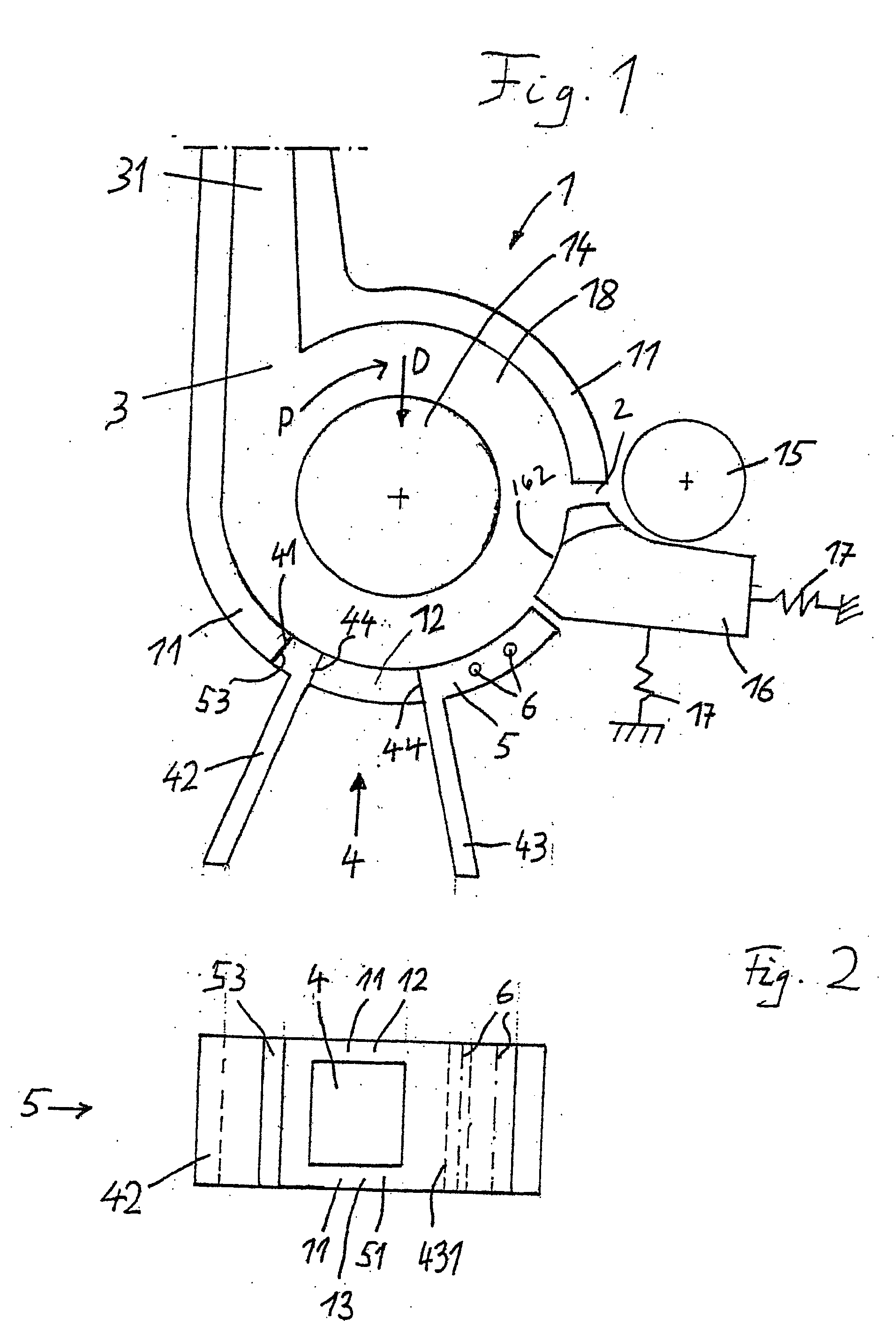
[0022] The sectional view of FIG. 1 illustrates a profile view of the invented disintegrator roll housing with an invented insert, wherein the disintegrator roll is absent from its casing. For the mounting of the disintegrator roll, the disintegrator roll housing 1 has a round opening 14, through which passes, in operational conditions, a shaft, upon which the disintegrator roll is fastened. The disintegrator roll housing 1 has a feed opening 2 through which the fiber band (not shown) to be disintegrated is transport...


PUM


Abstract

An exchangeable insert is proposed as auxiliary equipment for a housing of a disintegrating apparatus of an open-end spinning apparatus. The insert is adaptable, so that the disintegrator roll housing can be made to conform to various spinning conditions. In a partial zone, in accord with this proposition, the insert replaces a circumferential wall of the disintegrator roll housing, wherein the insert extends itself into to a zone of a contamination separation opening of the disintegrator roll housing. Its extension in the axial direction is so chosen, that it, at least partially, forms a portion of the circumferential wall of the disintegrator in the area of the contamination separation opening.

Description

FIELD OF THE INVENTION [0001] The present invention concerns a disintegrator roll housing, whereby an insert is placed in an area, following the feed entry of the band as seen in the direction of rotation of the disintegrating drive shaft and further concerns a procedure for the modernization of an open-end spinning apparatus, whereby an insert of the disintegrator roll housing can be removed and subsequently replaced. BACKGROUND OF THE INVENTION [0002] Disintegrator roll housings are known in multitudinous designs within the state of the technology, including the spinning units SE7, SE8 and SE9 of a rotor based spinning machine “Autocoro” of W. Schlafhorst AG & Co., 41061 Mönchengladbach, DE. The disintegrator roll housings of these spinning units consist essentially of individual segments, which are placed on a carrier plate. The individual segments, which are set on this carrier plate, thus form the circumferential wall of the distintegrator housing, particularly in the zone betw...

Claims


Application Information

Patent Timeline
IPC IPC(8): D01H4/32
CPCD01H4/32
Inventor HIRSCH, ALBERT
Owner RIETER INGOLSTADT SPINNEREIMASCHENBAU AG
Why Eureka
Try Eureka