Optical junction nodes for use in data center networks

a data center network and optical junction technology, applied in data switching details, multiplex communication, duplex signal operation, etc., can solve the problems of data communication between servers that are not co-located within the same rack experiencing excessive delay, data communication between such servers may also experience latency within the respective switches and/or routers, etc., to reduce the overall physical interconnectivity requirements reduce the cost and complexity of the data center network, and efficiently allocate bandwidth

Active Publication Date: 2012-12-20
HEWLETT-PACKARD ENTERPRISE DEV LP
View PDF4 Cites 18 Cited by
  • Summary
  • Abstract
  • Description
  • Claims
  • Application Information

AI Technical Summary

Benefits of technology

[0007]In accordance with the present application, data center network architectures, systems, and methods are disclosed that can reduce the cost and complexity of data center networks. Such data center network architectures, systems, and methods can employ physical optical ring network topologies, optical nodes, and optical junction nodes to efficiently allocate bandwidth within the data center networks, while reducing the overall physical interconnectivity requirements of the data center networks.

Problems solved by technology

Although the conventional data center networks described above have been employed to satisfy the operational requirements of many university, government, business, and financial service entities, such conventional data center networks have drawbacks.
For example, data communications between servers that are not co-located within the same rack may experience excessive delay (also referred to herein as “latency”) within the data center network, due in no small part to the multitude of switches and / or routers that the data may be required to traverse as it propagates up, down, and across the hierarchical architecture of the network.
Data communications between such servers may also experience latency within the respective switches and / or routers of the data center network due to excessive node and / or link utilization.
Further, because multiple paths may be employed to deliver broadcast and / or multicast data to different destinations within the data center network, such broadcast and / or multicast data may experience excessive latency skew.
Such latency and / or latency skew may be exacerbated as the size of the data center network and / or its load increases.
The hierarchical architecture of the data center network also generally suffers from increasingly complex but essentially fixed fiber cabling requirements, as the numbers of switches, routers, layers, and their interconnections are increased to handle the expansion of the data center network.

Method used


Image

  • Optical junction nodes for use in data center networks
  • Optical junction nodes for use in data center networks
  • Optical junction nodes for use in data center networks

Examples


Embodiment Construction

[0022]The disclosures of U.S. Provisional Patent Application No. 61 / 498,931 filed Jun. 20, 2011 entitled DATA CENTER NETWORK SWITCHING, U.S. Provisional Patent Application No. 61 / 554,107 filed Nov. 1, 2011 entitled DATA CENTER NETWORK SWITCHING, and U.S. patent application Ser. No. ______ filed Jun. 20, 2012 entitled OPTICAL ARCHITECTURE AND CHANNEL PLAN EMPLOYING MULTI-FIBER CONFIGURATIONS FOR DATA CENTER NETWORK SWITCHING, are incorporated herein by reference in their entirety.

[0023]Data center network architectures, systems, and methods are disclosed that can reduce the cost and complexity of data center networks. Such data center network architectures, systems, and methods can employ physical optical ring network topologies, optical nodes, and optical junction nodes to efficiently allocate bandwidth within the data center networks, while reducing the overall physical interconnectivity requirements of the data center networks.

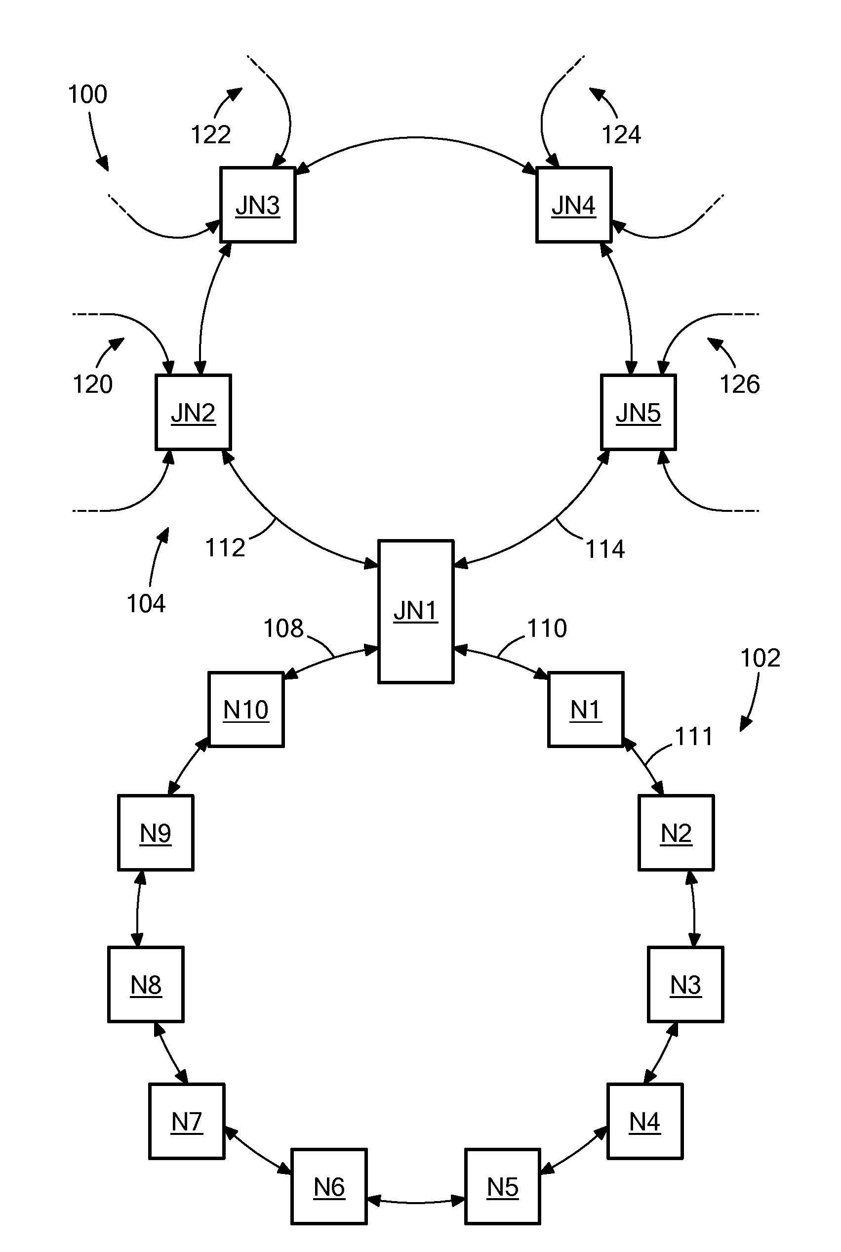
[0024]FIG. 1 depicts an illustrative embodiment of an ...


PUM


Abstract

Data center network architectures, systems, and methods that can reduce the cost and complexity of data center networks. Such data center network architectures, systems, and methods employ physical optical ring network topologies, optical nodes, and optical junction nodes to efficiently allocate bandwidth within the data center networks, while reducing the overall physical interconnectivity requirements of the data center networks.

Description

CROSS REFERENCE TO RELATED APPLICATIONS[0001]This application claims benefit of the priority of U.S. Provisional Patent Application No. 61 / 498,931 filed Jun. 20, 2011 entitled DATA CENTER NETWORK SWITCHING, and U.S. Provisional Patent Application No. 61 / 554,107 filed Nov. 1, 2011 entitled DATA CENTER NETWORK SWITCHING.FIELD OF THE INVENTION[0002]The present application relates generally to data center network architectures and switching technologies, and more specifically to data center network architectures, systems, and methods that employ optical ring network topologies, optical nodes, and optical junction nodes to efficiently allocate bandwidth within data center networks, while reducing the physical interconnectivity requirements of the data center networks.BACKGROUND OF THE INVENTION[0003]In recent years, university, government, business, and financial service entities, among others, have increasingly relied upon data center networks that incorporate racks of server computers ...

Claims


Application Information

Patent Timeline
Patent Type & Authority Applications(United States)
IPC IPC(8): H04B10/20H04L45/74
CPCH04J14/00H04L5/14H04J14/021H04J14/0213H04J14/0217H04J14/0238H04J14/0269H04J14/0275H04J14/0283H04J14/0228H04Q11/0005H04L49/351H04L45/745H04L12/18H04Q2011/0037H04J14/0267H04J14/022H04B10/275H04J14/0206
Inventor SPOCK, DEREK E.BARRY, RICHARD A.HUSAK, DAVID J.EVERDELL, PETER B.LI, RUODING
Owner HEWLETT-PACKARD ENTERPRISE DEV LP
Why Eureka
Try Eureka