
High-frequency laminated component and laminated high-frequency filter

a technology of high-frequency filter and laminated components, which is applied in the direction of structural fixed capacitor combination, association of printed circuit non-printed electric components, inductance, etc., can solve the problems of deterioration of filter characteristics (transmission characteristic and attenuation characteristic), failure to obtain desired transmission characteristics, and increase insertion loss, so as to reduce and prevent the generation of resonance points, reduce and prevent unnecessary coupling, and reduce the effect of siz

Active Publication Date: 2012-12-20
MURATA MFG CO LTD
View PDF6 Cites 30 Cited by
  • Summary
  • Abstract
  • Description
  • Claims
  • Application Information

AI Technical Summary

Benefits of technology

The present invention provides a high-frequency laminated component and a laminated high-frequency filter with superior characteristics. The invention reduces and prevents the generation of resonance points and increases in insertion loss by significantly reducing and preventing the formation of a series capacitor. The high-frequency laminated component includes a circuit function section, such as a filter, that has a predetermined frequency transmission characteristic. The component also includes inner-layer ground electrodes and parallel capacitors that are positioned between the input / output terminals and the inner-layer ground electrodes, which further improves the frequency characteristic and reduces the size of the component. The circuit function section includes electrodes patterns located on the insulating layers, and the use of a mounted component makes it easy to change the circuit devices and achieve a superior frequency characteristic. Overall, the invention provides a high-frequency laminated component with superior characteristics that reduces and prevents resonance points, increases in insertion loss, and improves frequency characteristic.

Problems solved by technology

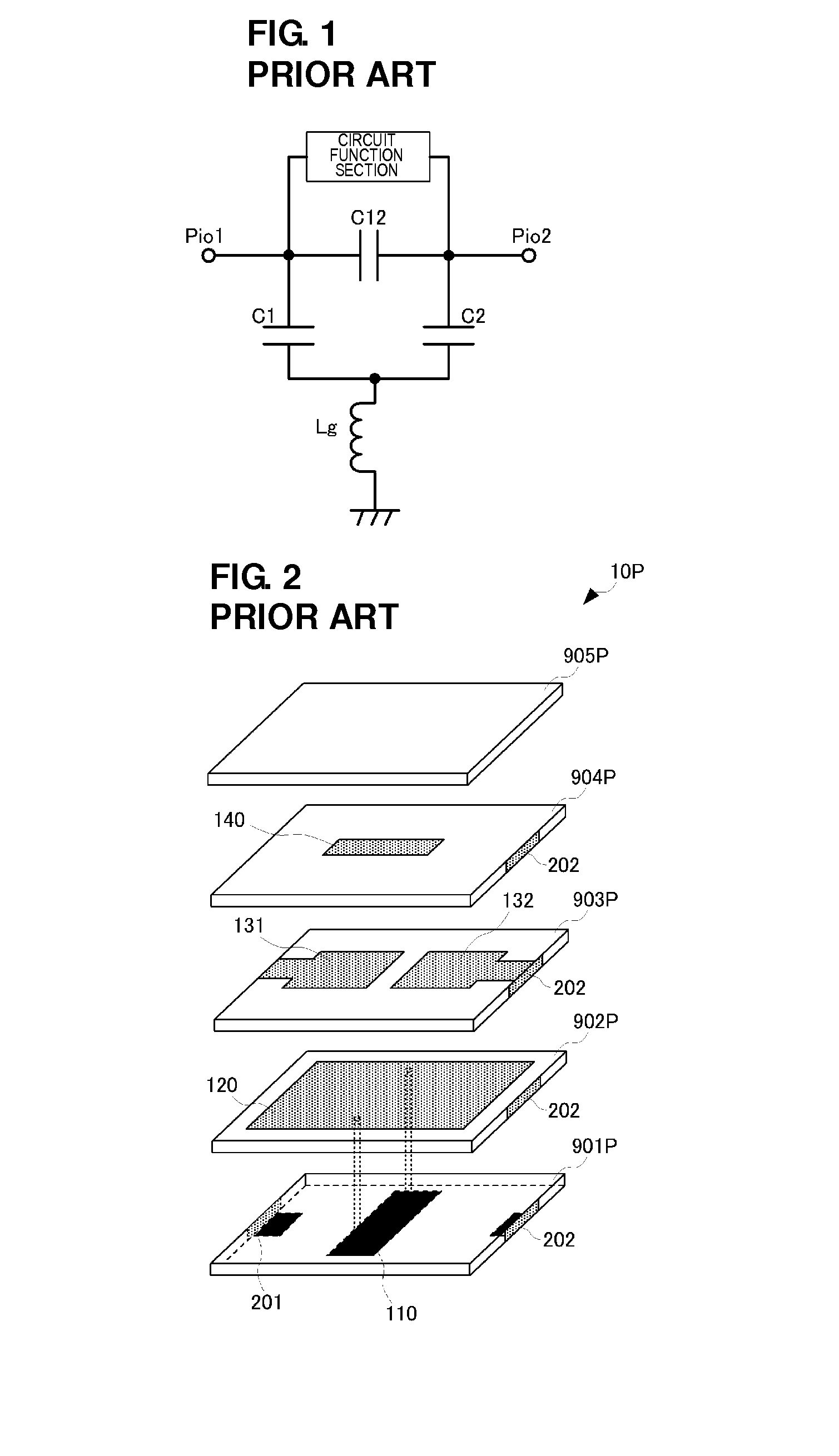
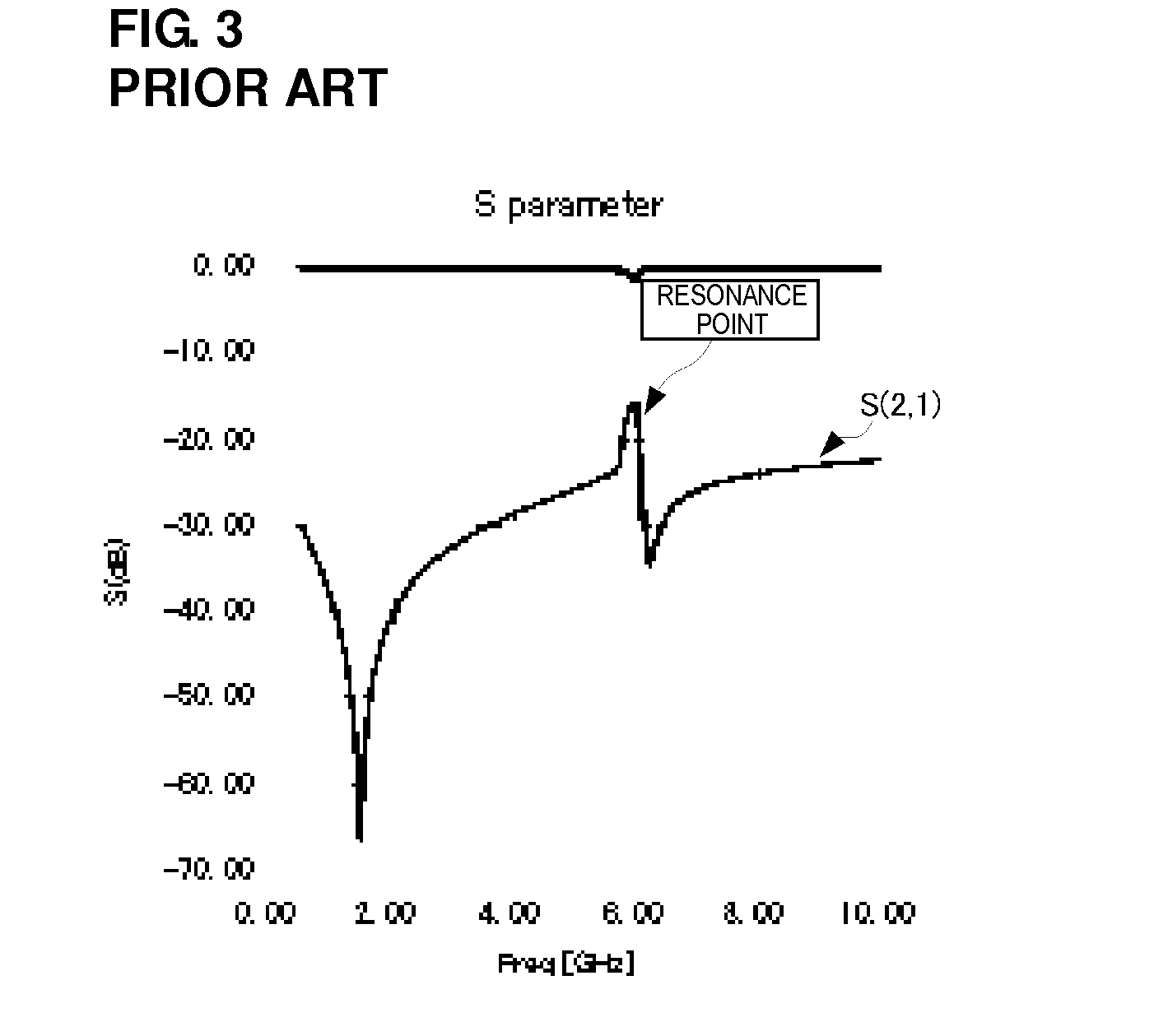
Therefore, a desired transmission characteristic fails to be obtained, even if the laminated structure configures a filter, such as a band pass filter, for example.
In the above-described structure, the electrode forming the skip-coupling capacitor exerts substantial influence on the coupling between the inductors, and the insertion loss is increased.
Thereby, characteristics of the filter (transmission characteristic and attenuation characteristic) are deteriorated.

Method used


Image

  • High-frequency laminated component and laminated high-frequency filter
  • High-frequency laminated component and laminated high-frequency filter
  • High-frequency laminated component and laminated high-frequency filter

Examples


Embodiment Construction

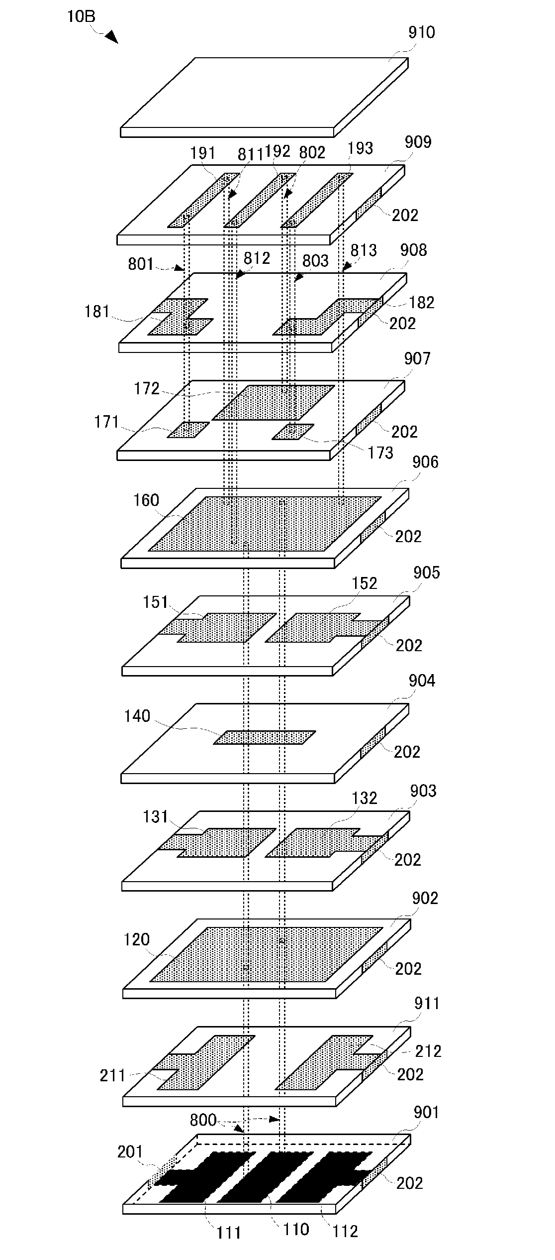
[0097]A high-frequency laminated component according to a first preferred embodiment of the present invention will be described with reference to drawings. In the present preferred embodiment, description will be made with reference to a band pass filter (BPF) as an example of the high-frequency laminated component. FIG. 5A is an external perspective view of the high-frequency laminated component of the present preferred embodiment, and FIG. 5B is a diagram illustrating a laminated configuration of the high-frequency laminated component of the present preferred embodiment. The high-frequency laminated component 10A illustrated in FIGS. 5A and 5B is a band pass filter including three stages of parallel LC circuits, and an equivalent circuit thereof is the same as the above-described one in FIG. 4A.

[0098]The high-frequency laminated component 10A is defined by a laminate 10A including ten laminated insulating layers 901 to 910, for example. Each of the insulating layers 901 to 910 def...


PUM


Abstract

A laminate defining a high-frequency laminated component includes a ground electrode on a bottom surface of a lowermost insulating layer. A second insulating layer includes an inner-layer ground electrode arranged over substantially the entire surface thereof. A portion from a third insulating layer to a fifth insulating layer is provided with a capacitor electrode defining a series capacitor of a ground impedance adjustment circuit and capacitor electrodes defining a first parallel capacitor and a second parallel capacitor. A sixth insulating layer has an inner-layer ground electrode provided over substantially the entire surface thereof. The inner-layer ground electrodes are arranged in electrical continuity with the ground electrode by via holes.

Description

BACKGROUND OF THE INVENTION[0001]1. Field of the Invention[0002]The present invention relates to a high-frequency laminated component realizing a desired circuit function by providing electrodes in predetermined patterns on a plurality of insulating layers, and also relates to a laminated high-frequency filter including the high-frequency laminated component.[0003]2. Description of the Related Art[0004]In the past, various types of high-frequency laminated components have been used in wireless devices, such as cellular phones. As indicated in Japanese Unexamined Patent Application Publication No. 8-46401, for example, a high-frequency laminated component has a laminated structure including a plurality of insulating layers.[0005]In the high-frequency laminated component, predetermined electrode patterns are formed on the plurality of insulating layers to form inductors and capacitors. Further, the inductors and the capacitors formed by these electrode patterns are connected by other ...

Claims


Application Information

Patent Timeline
Patent Type & Authority Applications(United States)
IPC IPC(8): H03H7/01H05K1/18
CPCH01G4/40H03H7/0115H03H7/09H03H7/1708H03H7/1775H03H7/1766H03H7/1791H03H2001/0085H03H7/1725H01F38/14H01F2038/146
Inventor TANIGUCHI, TETSUO
Owner MURATA MFG CO LTD
Learn More